
Ultimate Guide: Embedded System Design
25/05/2021, hardwarebee
Creating a well-tested reliable embedded software is important, especially in safety-critical applications. A great design starts with a well thought system design. Following the system design, embedded hardware design and software design will take place with high clarity. In this article we mainly focus on embedded system design.
Embedded system design is based on software development processes and life cycle, using any of the popular models such as the waterfall model, the V-Model and nowadays most of the software houses use the agile methodologies.
Embedded System Design Overview
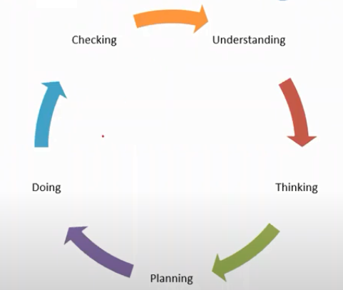
Why do we create software? This question is a basic question, the answer is to solve a specific problem based on some requirements. Another important question, how do we create software? The answer is in the following figure, which is an example of a software development life cycle. There are 5 stages in the following model, the waterfall model.
- Requirements Analysis
- Design
- Development
- Testing
- Maintenance
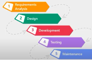
In the first stage, the requirements should be collected and the software requirement document is written. In the design phase, we answer the question “how to build the solution?”. In the SW development phase, we start to implement the software and write the code. In the testing phase, we verify the proposed solution to produce high-quality software. After deployment of the solution, we maintain it if needed in case of changing the requirements.
Our scope here is on the design phase, our input is system/requirement specification and, the output is the design document.
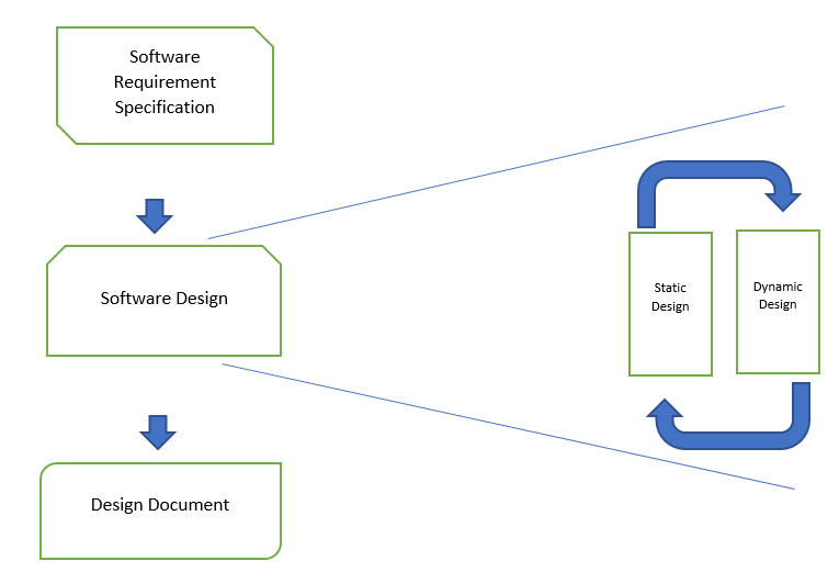
The Design document can be a physical Document or a code skeleton. There are two types of software design a static design or a dynamic design.
In the static design, you define the structure, the structure includes modules and how they connected. On the other hand, the dynamic design defines how the modules interact together.
As an example, in a football match, consider the plan of the team (e.g. 4-4-2) as the static design and consider how they move as the dynamic design.
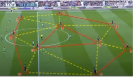
Another example from the definition of the real-time system, a real-time system is a system that has to perform a correct function at a correct time.
Static design is responsible for executing the correct function, on the other hand, the dynamic design enables the function to be executed at the correct time.
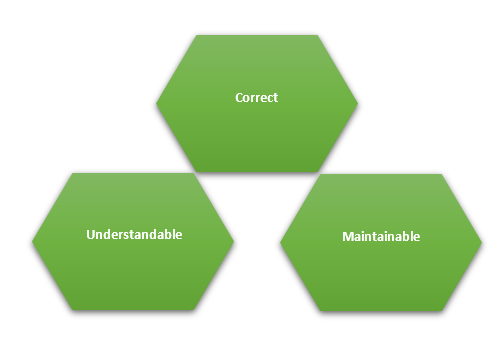
Embedded Software Design Characteristics
Good software design has three main characteristics. Your software design should be correct, meaning, that everything is correct and nothing is wrong from gathering, requirements (inputs), so your design solution should meet these requirements. The second one, the software design should be understandable, and it means that any stockholder should understand the design regardless of his/her background, however, we do a lot of reviews between the team members to clarify the design. The third characteristic of a good embedded software design is to be maintainable; we mean here that the system should allow editability, in case of changing the requirements, we can change the design without damaging any other part or any other component in the system.
Software Design Levels
When creating a design, it can be done through steps, as example, when facing a big problem, we try to solve it by cutting it into smaller parts “Divide and conquer approach”.
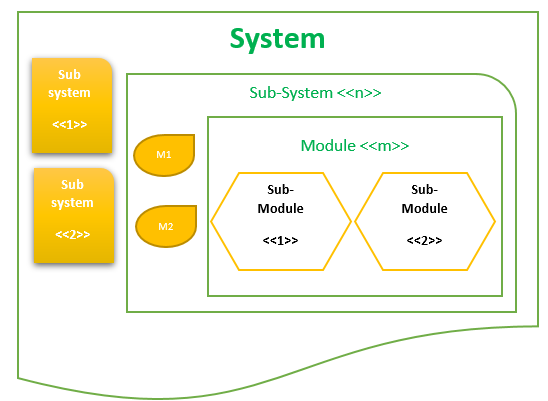
As you can see in the figure, we have divided the system into subsystems, and also have divided each subsystem into modules and submodules.
For example, consider you are working on a microcontroller project, we can map the design outputs to c code as
— System is the IDE Project
— Sub-system is the group of files
— Module contains on functions’ definition in 1 C file or more header files
— Sub-module contains data types, variables, and the implementation of the functions.
Pragmatic Software Design
To make your design pragmatic we should have
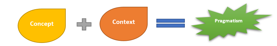
The Concept is what you have studied and your previous experience as a designer. The more concept, the better. The context is how you can use and apply your knowledge to achieve pragmatism.
The goal of pragmatic software design is to determine and organize how we reach the optimal solution. Keep in mind always the following slogan “if you fail to plan, you plan to fail”, so you need to organize and plan before implementing your solution.
Elements of Embedded software Design
There are some questions you should ask yourself before starting your design process
How to identify modules:
– using context diagram
OR
– using Super loop and block diagram
How to identify modules’ interfaces
– apply 4 rules in the software design process
How to identify dynamic design or behavior
– using interfaces classification
– using timing analysis
– do schedulable check
How to identify modules’ details
– using Pseudo code
– using state machines
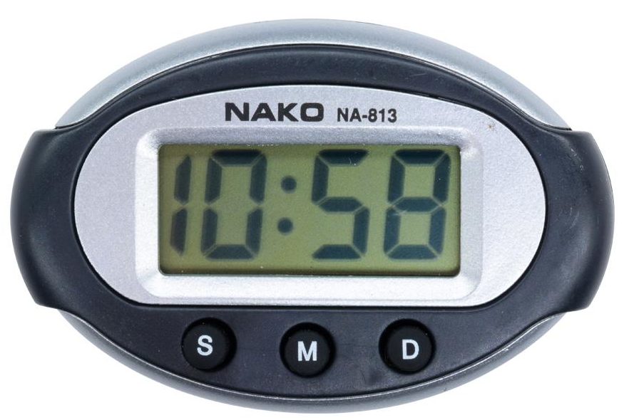
Case Study – A Digital Clock
This is a design example of a digital clock with 3 modes/buttons
- Normal
- Set hours
- Set mins
Let’s look at the first question “How to identify modules: ”
Context diagram
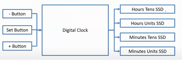
From the context diagram, we can understand what are the inputs and what are the outputs
Super Loop as a design tool
Identify modules of the digital clock:
Void main (void)
{
while (1)
{
pushButton.update(); // Input taks
TIME.update(); // Processing Task
sevenSegmentDisplay(); //Output Task
}
}
Block Diagram
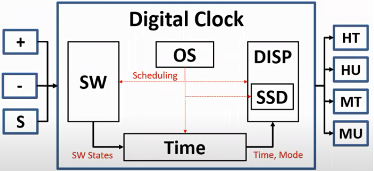
In the block diagram, we divide the modules in the context diagram. There is always an operation system (e.g. real-time system, while(1), simple scheduler)
In the figure, we have modules such as:
- Switches (SW) is used to set the hours, mins and change the modes
- OS is used (to set the rules of the software)
- Seven Segments Display (SSD) is used to display the time
- Time module is used to send the time and the mode to display (SSD)
- Display module (DISP) is used as a generic module to allow us to change display block e.g. from seven segments to LCD
from the static design Perspective, any module should have
- Initialization function is used to
Initialize hardware
Initializes data structures
Initializes both
- 1 or more update functions
Update something
Do the module logic
- 0 or more setter functions
Set something in the module
- 0 or more getter functions
Get something from the module

The above figure applies the rules to the digital clock use case
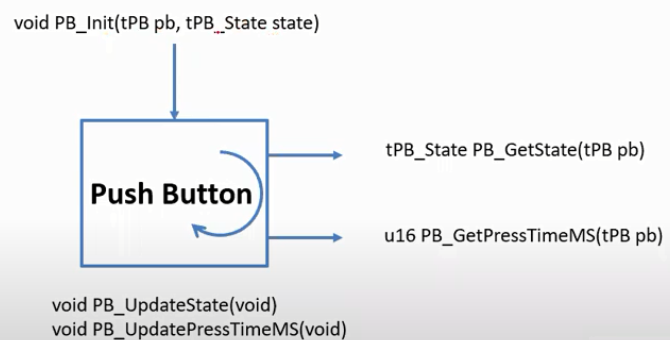
A push Button Module
This is another module in our system (push button)
The push button module is used to identify the state of the button to show us if it is pressed or not
Setter or a getter?
If we have 2 modules connected together
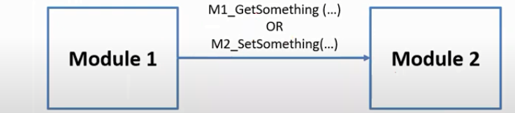
We have 2 options:
M1_Getsomething
- Implemented in M1 and called in M2
M2_SetSomething
- Implemented in M2 and called in M1
Modules’ Interfaces of the digital clock
Switch
- SW_Init
- SW_Update
- SW_GetState
OS
- OS_Init
- OS_Update
- OS_Sleep
TIME
- Time_Init
- Time_Update
- Time_GetTime
- Time_GetMode
DISP
- DISP_Init
- DISP_Update
SSD
- SSD_Init
- SSD_Update
- SSD_SetSymbol
- SSD_GetSymobl
- SSD_SetState
- SSD_GetState
From the dynamic design perspective, we can classify the functions into 4 types
- Initialization
Called just one time before using the module
- Task
Period or aperiodic and it is called by the operating system
- ISR
Period or aperiodic and it is called by the hardware
- Function
It is not like any of the above types and it can be called by any other function.
Similarities between static and dynamic design:
Initialization is the same in static and dynamic design. Update in the static design is task and ISR in the dynamic design. Setter and getter in the static design can be functions in the dynamic design.
To apply them in our use case
- pushButton_Init is an initialization function
- pushButton_UpdateState can be task or ISR
- pushButton_UpdatePressTimeMS is a task
- pushButton_GetState is a function
- PushButton_GetPressMS is a function
Timing Analysis of a function
We have many parameters to be used in timing analysis
E is the Execution time
- BCET is the best-case execution time (the max time to be done)
- WCET is the worst-case execution time (the min time to be done)
B is the blockage (interruption + preemption) that can be discovered after system integration
D is the deadline (based on the requirements)
P is the period (design choice)
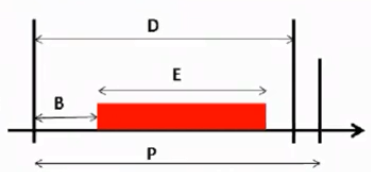
BCET <= WCET and B +E <= D <= P
Schedulability Check
If the functions are not periodic, change the period with the minimum interarrival time.
- Worst-case design (E = D = P)
No multitasking
- Relaxed worst-case design (E < D = P)
The first design check
- Blockage is considered after integration (B+E < P)
Schedulability check
Timing Analysis and Schedulability check the digital clock use case
The following table has the timing analysis and the Schedulability check of our use case
Conclusion
In this article we have introduced, how to create a pragmatic embedded software design step by step. Embedded software design is important to meet the requirements of any system software. What to do next? Try to implement apply the principles of embedded software design on any embedded system you know and then implement the system using any microcontroller.
References
Embedded Systems Architecture 2nd Edition, Author: Tammy Noergaard


