
The Ultimate Guide to IO-Link
18/08/2021, hardwarebee
What is IO-Link?
IO-Link is a point to point, industrial communications networking standard (IEC 61131-9) used for using short distance, bi-directional, digital, wired or wireless interface.
Its objective is to provide a connectivity between sensors and actuators to either a type of industrial fieldbus or a type of industrial Ethernet technological platform that for the growing market of industrial automation.
How Does IO-Link Work?
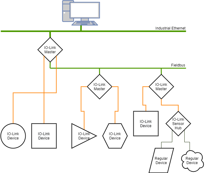
Figure 1 – Example of an architecture using IO-Link
An IO-Link system is composed of one IO-Link master and one or more IO-Link devices, which can be sensors and/or actuators. The role of the IO-Link master is both to provide the interface to the higher-level controller (PLC) and to manage the communications with the connected IO-Link devices.
In general, the IO-Link master can have one or more IO-Link ports, to which only one IO-Link device can be connected at a time. Alternatively, the master can also be an intermediary hub, allowing classic switching sensors and actuators to be connected and integrated into the system.
As for the IO-Link device, it can be an intelligent sensor, actuator, hub or, due to the bidirectional communication capabilities, a mechatronic component (for example, a gripper or a power supply unit with an IO-Link connection). Any IO-Link device is intelligent because that device has identification data (some possible examples are: a type designation, a serial number, or parameter data like switching delays, sensitivities, and characteristic curves) and detailed diagnostic data.
This data can be read or written via the IO-Link protocol by the PLC during operation, and it is often used for preventive maintenance and servicing. For example a sensor could be integrated into an IO-Link system and inform it when some criterion has been met, based on which the system can then emit a warning or alert the responsible engineer to take a closer look.
The identification parameters of the IO-Link devices are device- and technology-specific, which is why parameter information is stored in the form of an IODD (IO Device Description), using XML (the eXtensible Markup Language). The IO-Link community provides appropriate interfaces as an IODD Finder, which can then be used by engineering or master tools to locate and present the appropriate IODD for a device.
IO-Link Application Examples
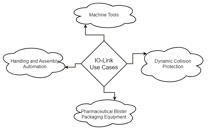
Figure 2 – Use cases for IO-Link
Here are a few use cases for IO-Link and the benefits of using this technology for each of them:
Machine Tools (automatic setting of sensor parameters)
IO-Link offers a clear advantage for initial parameter setting as well as for parameter setting when a unit needs to be replaced.
A machine tool contains multiple sensors for detecting pressures, levels and temperature. The sensors used today are set manually using keys and a 7-segment display. Initial parameter setting and resetting when a unit needs to be replaced is time-consuming and costly. Nor can the risk of a parameter setting error be precluded.
IO-Link capable sensors are identifiable through their Vendor and Device ID. The program recognizes the connected sensor, checks for correctness and sets the sensor parameters using the associated parameter record. With this solution even sensors from different manufacturers can be used.
IO-Link also offers a solution for the standard sensors installed on the machine: the signals are collected in a simple way using IO-Link sensor hubs and passed along to the controller.
Some of the benefits to the customer are:
- Fast initial set up of the machine
- Drastically simplified sensor replacement when failures occur, shorter downtimes
- End use does not have to worry about setting sensor parameters
- Greater security through errorless parameter setting
- Centralized documentation of the parameter sets
- Simple connection of standard sensors using IO-Link
- Remote diagnostics possible down to the sensor level
Simplified installation of handling and assembly automation
IO-Link enables a drastic simplification of installation, since only a simple standard sensor cable is used.
A valve assembly line uses a 20-stage process to fully automatically assemble various components such as plastic parts, O-rings and compression springs into ready-to-install and seal-tested valves. An industrial RFID system with read stations at a total of 17 locations provides information exchange between material flow and the controller.
A large number of standard sensors such as diffuse photoelectric, inductive proximity switches and cylinder switches are also used, whose signals need to be carried to the controller in as simple a manner as possible. On the actuator side a larger number of parallel wired pneumatic valve terminals need to be connected.
The system is strictly modular, and each module needs to be capable of being added, started up and transported independently.
Just connecting the IO-Link capable RFID devices results in an enormous simplification of the installation. In contrast to the previous installation, now only a simple standard sensor cable such as the one already found on the equipment needs to be used. This connects the RFID device to the closest IO-Link Master over the shortest distance and is ready to plug in.
The use of IO-Link valve terminal plugs along with IO-Link sensor hubs for collecting standard sensor signals means on the sensor and actuator side that parallel wiring is for the most part replaced by the serial IO-Link.
Some of the benefits to the customer are:
- Drastically simplified connection of RFID readheads, valve terminals and standard sensors
- Most parallel wiring replaced by IO-Link
- Modular construction of the equipment, modules linked via connectors
- Ready to plug in, no cable assembly and no tedious connecting of cable to terminal clamps.
- Drastically simplified electrical connection already accomplished at the time of installation by the mechanical personnel.
- Saves resourced: Less copper, no wasted worker time
Intralogistics (dynamic collision protection)
IO-Link enables dynamic sensor parameter setting during the production process.
Overhead conveyors have varying braking distances depending on their load and travel speed. With conventional anti-collision approaches therefore the setting is for maximum load and maximum travel speed. This means the speed change and vehicle stop point is often set much earlier than necessary, which is not an ideal solution.
The trigger points for speed change and vehicle stop can be changed dynamically at any desired time using IO-Link and depending on the load and travel speed.
Some of the benefits to the customer are:
- Optimizing of collision positions
- Reduction in creep speed travel cycles
- Faster base speed
- Greater system efficiency
Validation in pharmaceutical blister packaging equipment
IO-Link assists in validation of equipment and machines down to the smallest sensor and actuator.
Different materials are used in the feeding of deep-draw film. The differentiation between aluminium deep-draw film and transparent film should take place right at the feed point of the machine. All the settings and adjustment to the sensor should be reported to the controller. Sensor operation should be possible using various access codes.
An optical sensor makes the distinction between aluminium and transparent plastic film. The returned degree of transmission is accomplished using IO-Link in the form of a percent value from 0% to 100% (high-transparent to opaque). IO-Link is used to report all direct operator actions on the sensor to the controller and log them there.
Some of the benefits to the customer are:
- Each film change is detected by the sensor and logged in the controller
- A broad material distinction is made at the earliest possible point in time
- Sensor parameters such as contamination level can be logged during the production process
- The sensor can be set directly from the controller
- Machine and process validation down to the lowest automation level
IO Link Benefits
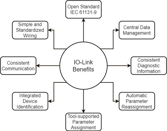
Figure 3 – Benefits summary of IO-Link
The IO-Link system offers decisive advantages as a digital interface for connecting sensors/actuators:
Open standard according to IEC 61131-9
- Devices can be integrated in the same way in all commonly used fieldbus systems and automation systems
Tool-supported parameter assignment and central data management
- Fast configuring and commissioning
- Easy creation of up-to-date plant documentation, including for sensors/ actuators
Simple, standardized wiring and a significantly reduced variety of interfaces for sensors/actuators
- Standardized uniform interface for sensors and actuators irrespective of their complexity (switching, measuring, multi-channel binary, mixed signal, etc.)
- Reduced variations and inventory
- Fast commissioning
- Reduced space requirement
- Any combination of IO-Link devices and sensors/actuators without IO-Link on the IO-Link master
Consistent communication between sensors/actuators and the controller
- Access to all process data, diagnostic data, and device information
- Access to device-specific data
- Remote diagnostics supported
Consistent diagnostic information down to the sensor/actuator level
- Reduced effort for troubleshooting
- Minimized failure risks
- Preventive maintenance and optimization of maintenance and maintenance scheduling
Dynamic change of sensor/actuator parameters by the controller or the operator on the HMI
- Reduced downtimes for product changeover
- Increased product diversity of the machine
Automatic parameter reassignment for device replacement during operation
- Minimized downtimes
- Device replacement by untrained personnel without additional tools
- Prevention of incorrect settings
Integrated device identification
- Identification of the embedded devices
- Ensuring the quality of results in production and manufacturing in the event of device replacement
Technical Specifications
Protocol
The IO-Link protocol consists of communication ports, communication modes, data types, and transmission speeds.
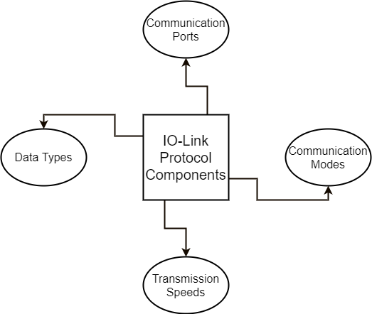
Figure 4 – IO Link Protocol Components
Operating Modes
The IO-Link ports of the master can be operated in the following modes:
- IO-Link: In “IO-Link” mode, the port is used for IO-Link communication.
- DI: In “DI” mode, the port behaves like a digital input.
- DQ: In “DQ” mode, the port behaves like a digital output.
- Deactivated: “Deactivated” mode can be used for unused ports.
Transmission Rate
Three transmission rates (baud rates) are specified for IO-Link mode in IO-Link Specification V1.1:
- COM 1 = 4.8k baud
- COM 2 = 38.4k baud
- COM 3 = 230.4k baud (optional according to Specification V1.0)
An IO-Link device supports only one of the defined data transmission rates. According to Specification V1.1, the IO-Link master supports all data transmission rates and adapts itself automatically to the data transmission rate supported by the device.
Response Time of the IO-Link System
The response time of the IO-Link system provides information about the frequency and speed of the data transmission between the device and master. The response time depends on various factors.
The device description file IODD of the device contains a value for the minimum cycle time of the device. This value indicates the time intervals at which the master may address the device. The value has a large influence on the response time. In addition, the master has an internal processing time that is included in the calculation of the response time.
Devices with different minimum cycle times can be configured on one master. The response time differs accordingly for these devices. That is, the response time of the different devices on a master can differ significantly.
When configuring the master, you can specify a fixed cycle time in addition to the device specific minimum cycle time stored in the IODD. The master then addresses the device based on this specification. The typical response time for a device therefore results from the effective cycle time of the device and the typical internal processing time of the master.
Transmission Quality
IO-Link is a very robust communication system. This communication system operates with a 24V level. If transmissions fail, the frame is repeated two more times. Only after the failure of the second retry does the IO-Link master recognize a communication failure and signal this to the higher-level controller.
Data Types
Four basic data types are available:
- Process data → Cyclic data
- Value status → Cyclic data
- Device data → Acyclic data
- Events → Acyclic data
Connector
Connection technology in IP65/67
For the connection technology in IP65/67, one possibility that has been defined is an M12 plug connector, in which sensors usually have a 4-pin plug and actuators a 5-pin plug. IO-Link masters generally have a 5-pin M12 socket.
The pin assignment is specified according to IEC 60974-5-2 as follows:
- Pin 1: 24 V
- Pin 3: 0 V
- Pin 4: Switching and communication line (C/Q)
Besides the IO-Link communication, these three pins are also used to supply the device with at least 200 mA of current.
Port types in IP65/67
The specification distinguishes two types of ports for the IO-Link master:
- Port Class A (Type A): In this type, the functions of pins 2 and 5 are not specified. The manufacturer defines these functions. Pin 2 is usually assigned with an additional digital channel.
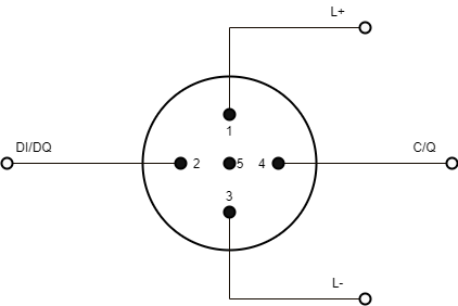
Figure 5 – Port Class A Pin assignment
- Port Class B (Type B): This type provides additional supply voltage and is suitable for the connection of devices that have an increased power demand. In this case, pins 2 and 5 are used to provide additional (galvanically isolated) supply voltage. A 5-conductor standard cable is required in order to use this additional supply voltage.
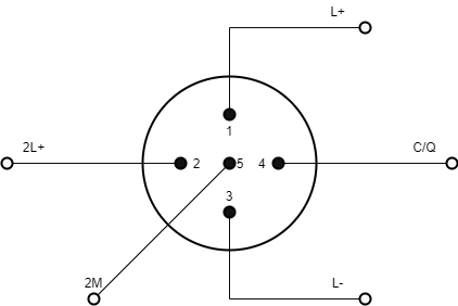
Figure 6 – Port Class B Pin assignment
Connecting Cable
The device is connected to the master via unshielded 3 or 5-lead standard cables with a length of at most 20m and cross-section >= 0.34 mm2. Shielding is not necessary.
Likewise, no specific guidelines have to be followed when laying the cables.


