The Ultimate Guide to RTL Design
11/03/2021, hardwarebee
This article provides an overview of Register Transfer Level (RTL) Design, it describes the fundamentals of RTL design and the process of RTL design. The article will also discuss RTL synthesis, RTL for synchronous and asynchronous design, RTL simulation, RTL in FPGA and ASIC and RTL design tools.
What is RTL Design?
Register Transfer Level (RTL) is a representation of the digital circuit at the abstract level. There are two elements in digital circuits: Sequential Circuit (Flip-Flop) and Combinational Circuit (Gates), with the help of these two elements, a digital designer can implement any circuit, i.e., adder, multiplier, counter, memories, and state machines. There are two commonly used variants of the RTL — namely: Verilog and VHDL, which a digital design engineer can represent their logic/functionality of the design in a simple text entry language.
Before the RTL invention, engineers designed a complete functionality as a circuit — schematic entry. You could imagine if someone had to design a 32-bit adder, he had to design all the logic in gates, this made the design a cumbersome job with high level of errors. RTL design convert this self-designing job to an easy automated process, in which a designer can write functionality of the design in the language of his choice, and a tool convert all of his design into the equivalent combinational and/or sequential circuit.

Figure 1: Code Snippet for D Flip-Flop
Figure 1 shows the code for the single-bit flip flop and one-bit inverter. An RTL synthesizer tool can easily convert the above code into the following one-bit D Flip Flop.

Figure 2: Alternative logic for the D-FF RTL with Reset
Figure 2 shows the combinational and sequential logic of the circuit explained in Figure 1. Similarly, one can implement the alternative digital circuit by writing a small piece of the code, quickly increase the size of the datapath and increase the number of inputs and outputs connections, make the control logic with the help of RTL design with the zero effort requires at the gate level/ circuit-level design.
The most crucial element in RTL design is the synthesizer’s role in translating your design into the respective circuit. Design a synthesizer itself is big domain companies like Xilinx and Synopsys invested millions in designing their synthesizer. This article will talk about the synthesizer briefly to understand the synthesizer’s role and how it converts the code into the circuit.
RTL Synthesis
RTL synthesizer primary responsibility is to convert the code into the gate-level netlist. This is a automated process; a tool has all the standard libraries definitions that can manipulate the respective gate-level netlist, which is an equivalent of your design in RTL. Synthesize tools can also do circuit optimization, power estimation, as well as timing analysis.
RTL Timing Analysis
For digital design, timing analysis can be performed at three different levels of abstraction:
- RTL level
- Gate level
- Layout level
Performing timing analysis at the RTL design level is a faster and cost-effective approach than waiting to find the same problems during timing analysis at the gate-level, layout-level, or fabrication.
Timing analysis at the layout level will always be more accurate, but it is an expensive and tedious job. Designers always try to avoid making timing changes at the layout level because of the cost. The iteration at the layout level is an expensive process.
The bests stage to timing analysis and quickly identify the path that causes timing problems is at the RTL level. Modern synthesize tools can perform the Static Timing Analysis (STA) of the design to find the potential timing issue that later causes the design’s metastability and negative slack.
RTL for Synchronous vs Asynchronous Logic
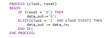
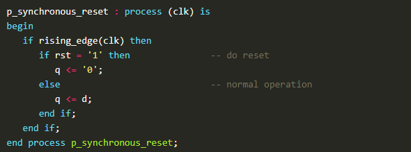
RTL can be used to design any digital circuit, either combinational or sequential. Similarly, RTL logic can also implement the asynchronous (event-based) or synchronous (clock) based logic. Figure 3 shows TL logic for the asynchronous logic where the circuit can be reset based on the event-based reset logic in that code that is independent of any other event. Figure 4 shows synchronous logic in which events depend on the clock synchronization. So, the RTL can be used for designing any circuit from asynchronous to synchronous.

Figure 3: Asynchronous RTL Logic

Figure 4: Synchronous RTL Logic
RTL Simulation
A good design that can meet the timing requirements is one part of the flow, and the design’s verification is the second part. There are RTL design simulators like Modelsim used for the verification of the design through simulation and debugging. These tools support mixed-language: VHDL, Verilog, SystemVerilog Simulator, support for the latest Verification Libraries, including Universal Verification Methodology (UVM), supports the latest Xilinx, Intel, Microsemi FPGAs. These tools can use UVM Toolbox, UVM graph, Class Viewer, Transaction streams and data to allow visual mapping and debugging designs based on OVM/UVM class libraries. They have built-in debugging tools that provide code tracing, waveform, dataflow, FSM window, coverage, assertion, and memory visualization capabilities and have advanced code and functional coverage capabilities.
RTL Usage in FPGA/ASIC Design Flow
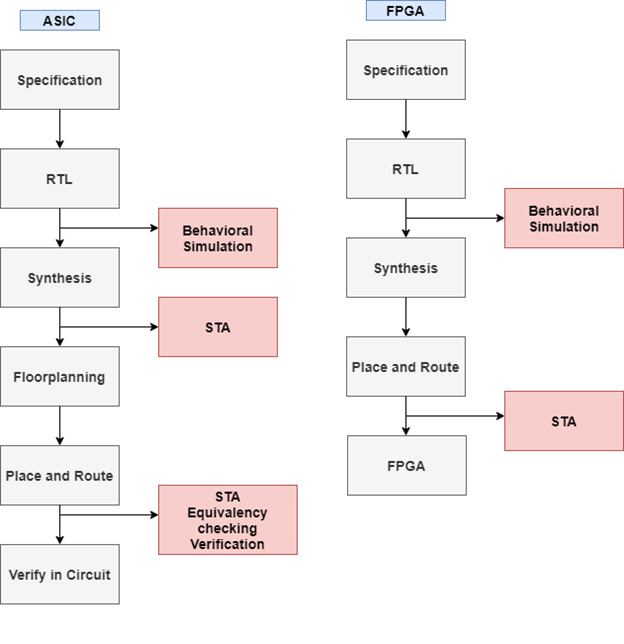
The advancement in the RTL languages RTL design flow is also part of the ASIC design flow. Instead of designing the ASIC from scratch, which also involves writing the libraries, the designer can write the functionalities of these circuit in RTL and generate the gate-level netlist, that further used to make the layout for the ASIC design. Figure 5 shows the design flow for ASIC and FPGA design. Both have the same initial design flow starting from the design specification and RTL. Either you want to do the RTL for FPGA and ASIC, the RTL design will remain the same. The difference starts after synthesizing FPGA does not require designer efforts to do floor planning and place and route instead done by the tool. ASIC designer needs to do the floor planning and route to optimize the design for better performance.

Figure 5: RTL design flow for FPGA & ASIC
RTL Design Tools
The major players in the area of RTL tools are the following:
- Xilinx/AMD ─ Vivado
- Intel/Altera ─ Quartus
- Synopsys ─ RTL Architect
- Cadence ─ Genus (RTL synthesis tool)
RTL Design FAQ
What is RTL design?
RTL (register-transfer level) design is a hardware design methodology that describes the behavior of digital circuits in terms of the flow of data between registers, and the operations that are performed on that data as it moves through the circuit.
What are the benefits of using RTL design?
RTL design allows designers to create digital circuits that are easier to understand, debug, and verify. It also allows for faster design iteration, as changes can be made at the RTL level rather than requiring changes to be made at the gate-level.
What tools are used in RTL design?
RTL design typically involves the use of hardware description languages (HDLs) such as VHDL or Verilog, as well as design tools such as synthesis tools and simulation tools.
How does RTL design differ from gate-level design?
RTL design focuses on the behavior of the circuit, whereas gate-level design focuses on the physical implementation of the circuit using logic gates. RTL design is a higher level of abstraction, allowing for easier design and modification, while gate-level design is more detailed and specific.
Can RTL design be used for all types of digital circuits?
RTL design is generally used for digital circuits that are relatively simple and have a small number of inputs and outputs. For more complex circuits, other design methodologies may be more appropriate.


