
Instrumentation Amplifier
04/09/2021, hardwarebee
Instrumentation amplifier is one of the most commonly used circuit topology for the purpose of subtracting 2 signals and amplifying the difference signal. Instrumentation amplifiers provide high gain for the differential input, that is the difference between V1 and V2 inputs, whereas they also alleviate problems in difference amplifiers caused by common mode inputs. There are a number of different instrumentation amplifier circuitries but the most common and robust design is shown in Figure 1. In this article, we will examine the instrumentation amplifier structure shown below.
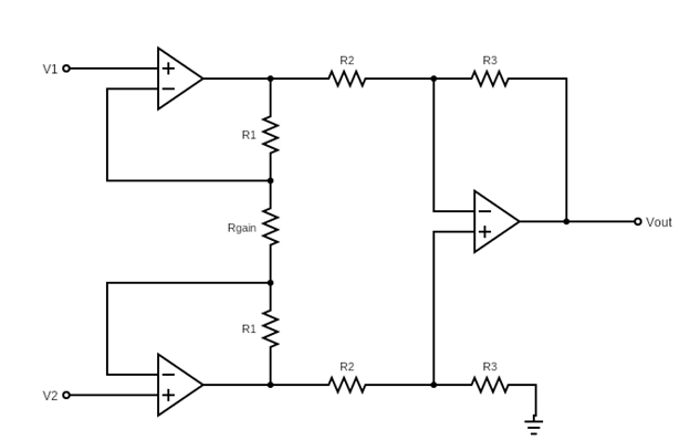
Figure 1: Instrumentation Amplifier
Benefits and Practical Use
Instrumentation amplifiers have high common mode rejection ratio (CMRR), yet still provide high differential gain due to their circuitry. In other words, the common mode signal is suppressed better in this topology compared to difference amplifiers. One application of this system is noise reducing. Instrumentation amplifiers perform very well in reducing the system noise. For instance, consider the V1 and V2 are connected to 2 different sources at a high distance. The cables carrying the signal will cause electrical noise due to the distance. If both cables are made of the same material with the same electrical features, then statistically the random noise will have similar characteristics in both inputs. Therefore, this noise can be considered as common mode signal. As a result, the instrumentation amplifier topology would suppress the noise because it is a common mode signal. The noise removing feature of instrumentation amplifiers is facilitated widely, especially in transducers.
Another important benefit that instrumentation amplifiers provide is high input impedance. Op-amps have infinite input resistance. In instrumentation amplifier topology, we have op-amp inputs directly connected to input sources. Also, we connect 2 inputs and make use of their difference signal. Therefore, input resistance goes to infinity. This prevents the impedance matching problem. Especially in biomedical applications, where the input signals are the signals obtained from body, this feature is very important.
Moreover, instrumentation amplifiers provide low DC offset. DC offset can cause problems in your application because the input signals are shifted by DC signals at the output and if your design requires no offset at the output, you may need to add another stage at output to get rid off of this offset. More stage and more elements mean increased cost in design.
In addition, instrumentation amplifiers are stable and robust designs. Stability is a desired property in design because your input signals may vary from one application to another, and if your design works perfectly for particular sources but fail for other sources, then this is a problem.
In the design shown in Figure 1, the circuit voltage gain Vout/V2-V1 can be adjusted by adjusting Rgain. This allows flexibility in your applications. You can connect a potentiometer there and adjust the circuit gain until you obtain the desired output voltage.
Circuit Analysis
In this part of the article, we will investigate how instrumentation amplifiers work and calculate the output voltage gain. As shown in Figure 2, we can roughly separate the design into 2 parts: stage 1 and stage 2 (difference amplifier). Vout1 and Vout2 branches are connected to the input of difference amplifier design in the second stage. Therefore, we need to first find Vout1 and Vout2 and then apply difference amplifier characteristics to these inputs.
Stage 1
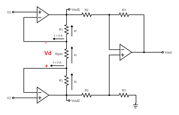
Figure 2: Instrumentation Amplifier with current directions shown
This stage encloses 2 amplifiers and 3 resistors, connected between inputs V1 and V2 and outputs Vout1 and Vout2.
First, let’s take a look at the V– node of the upper amplifier in the first stage. The amplifiers are assumed to be ideal, therefore their open loop gain is infinite. So, we can assume the voltage at V+ equals to the voltage at V–. Therefore, we can write V–= V+=V1. Similarly, we can write V–= V+=V2 for the bottom amplifier in the first stage.
As shown in the figure, no current can flow into amplifiers from their inputs because op-amps have infinite input resistance at their inverting and non-inverting inputs. Therefore, the current coming from R1 has nowhere else to flow to besides towards Rg. Similarly, the current coming from Rgain has to flow through R1 of the bottom amplifier. Thus, the current flowing from upper R1, Rgain and lower R1 resistances is the same current. Now that we set these, we can find Id expression using the difference signal.
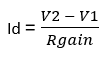
and define V2-V1 = Vd, the differential input signal
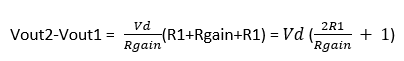
So, the voltage drop between Vout1 – Vout2 can be simply written as Id.R
Second Stage (The Difference Amplifier Stage)
Now that we found Vout2-Vout1, we can move on to the second stage. Vout2-Vout1 is the input to the second stage and it is actually a difference amplifier. The second stage is in fact a difference amplifier with differential input of Vout2 – Vout1. In order to simplify our calculations, first we will consider a simple difference amplifier and find it’s voltage gain. And then apply
![]()
to the result we will find in the second stage.
Consider the difference amplifier in the Figure 3 below. Let us calculate Vout for a difference amplifier with inputs V1 and V2, then replace the result in our expression above.
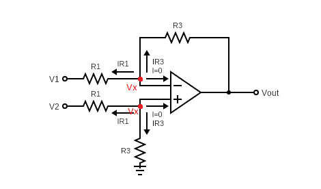
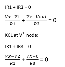
Figure 3: Difference Amplifier
We apply Kirchhoff’s Current Law at V– and V+ nodes. It should be noted that the op-amp is ideal, therefore we can write V– =V+=Vx for simplicity.
KCL at V– node:
Subtract these 2 equations from each other to get rid of Vx.
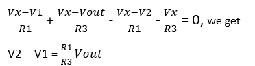
Now, going back to our original circuit, V1=Vout1 and V2=Vout2 for the difference amplifier stage (second stage). Therefore,
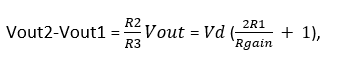
where Vd = V2-V1 as we found from the 1st stage above.
We get
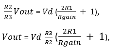
where Vd = V2-V1, the differential input.


