
Flyback Converter
30/11/2021, hardwarebee
The purpose of the flyback converter is to convert one form of electricity to another. Design of flyback converter is similar to a switch mode power supply and converts signals from AC to DC and DC to DC. Flyback converter applies the concept of non-linear switching supply. The main principle behind the design if flyback converters is the use of flyback transformer that stores magnetic energy and performs the function of inductor. The main purpose of this article is to present the concept of a flyback converter and it’s operation.
Flyback Converter Basics
The main reason of using the flyback converters is to convert power from AC to DC by using the galvanic isolation in outputs and inputs. Flyback converters store the energy in the tenure when current is flowing through the circuit and release power when power is removed. Flyback converters perform the operation of isolated switching converter if they are used with step down or step-up transformers. Flyback converters can be used for regulation of the multiple output voltages for different input voltages. The design of flyback converters is simple and less complicated as compared to other power supply circuits for switching. The design of Flyback converters uses on/off action of the switch and the word “Flyback” is used to demonstrate it.
Flyback Converter Design
The following are the electric components of flyback convertors generic design
- Flyback transformer
- Switch
- Rectifier
- Filter
- Control device
The purpose of using control device in Flyback converter design is to drive the switch and perform the function of regulation. The main objective of using the ON and OFF switch is to magnetize or demagnetize the transformer. In flyback converters, FET or MOSFET or a basic transistor performs the function of switch.
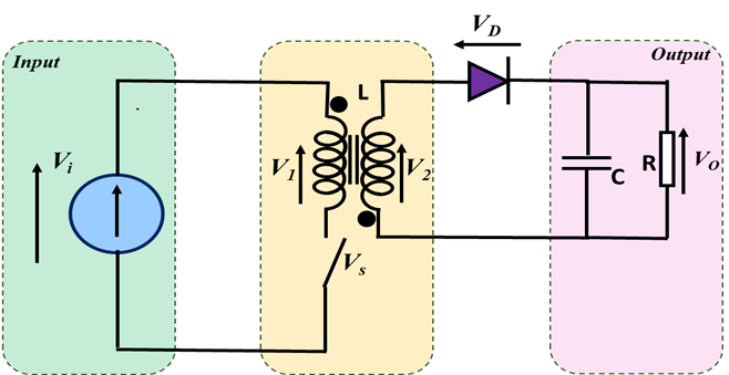
Figure 1: Flyback Converter Design
The purpose of using a rectifier in flyback converter is to rectify the voltage of the secondary winding so that pulsating DC output is produced. The rectifier also performs the function of disconnecting load from winding of the transformer. The capacitor filters the rectifier output voltage and increases the DC output level as per the desired application. The Flyback transformer stores the magnetic energy and acts as an inductor in flyback circuit. The design of flyback transformer uses two coupled inductors as primary and secondary windings. The operating frequency of flyback transformer is nearly 50KHz.
Design Calculations
Flyback converter design calculations are performed by computation of turns ratio, duty cycle, and primary and secondary current. Turns ratio has an impact on primary and secondary winding current and duty cycle.
Working Principle
Flyback converters operate on the basis of switch mode power supply (SMPS) mode. In case when switch is in ON position, there is no energy flow from input to load. The primary winding would store the energy in such condition and drain voltage would be zero. The energy is stored as magnetic inductance of the transformer and the rise in level of current is linear and the operation of diode is performed in reverse biased condition in such case. In this scenario, there would be current flow in secondary winding capacitor used at output stores the entire energy.
In case when switch is in OFF position, there is energy flow from input to load due to altering magnetic field and changing polarity. In such condition, the process of rectification also starts and voltage is rectified. In this scenario, there would be energy flow from core to load and it would be rectified. The process continuous till entire energy is depleted or switch is positioned back to ON state.
Flyback Converter Topology
The advantage of flyback converter topology is the fact that it is easily adaptable, flexible, used for SMPS (switch mode power supply) design. In addition, performance characteristics of flyback converter topology is very that gives an advantage to many applications.
The performance characteristics of the flyback converter topology are shown below.
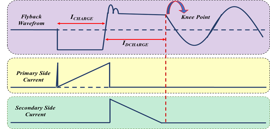
Figure 2: Flyback Topology performance characteristics
The output voltage of flyback converters is regulated by adjusting the on/off actions of primary winding. Additional winding of transformer would be used to isolate the input and output.
Flyback Topology SMPS
The topology of flyback SMPS needs less components for implementation. The operation of topology of flyback SMPS is possible for AC or DC source and uses the MOSFET in its circuit. The operation of topology of flyback SMPS depends on position of MOSFET. Topology of flyback SMPS operates in continuous or discontinued mode.
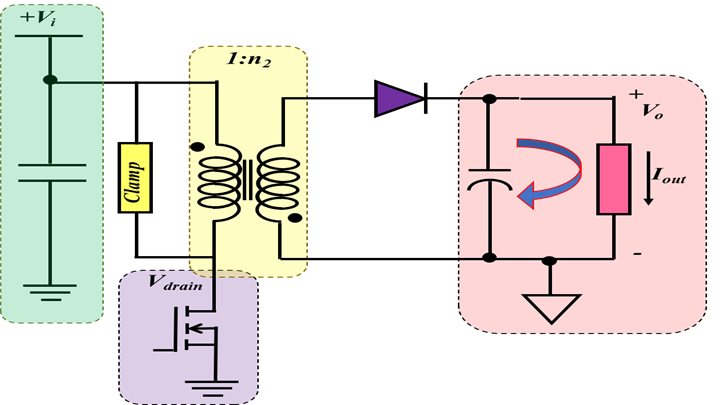
Figure 3: Flyback Topology SMPS
SMPS Flyback Transformer Design
SMPS flyback transformer design is commonly used because of its benefits of low cost, better efficiency, and simple design. SMPS flyback transformer design isolates the primary and secondary winding of the transformer as well.
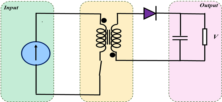
Figure 4: Transformer Switch is ON
SMPS flyback transformer design provides advantage that current doesn’t flow through the primary and secondary winding simultaneously.
Figure 5: Transformer Switch is OFF
Important parameters in SMPS flyback transformer design include maximum output load voltage, operating ranges, input and output voltage ranges, power delivery capability, and the characteristics of flyback cycle.
Applications
Following are important application of flyback converters:
- Flyback converter finds application in TV and PC that has low power of 250W
- Flyback converters are used in stand-by power supplied in PC.
- Flyback converter are used in isolated gate driver circuits
- Flyback converter is also used in multiple input output supplies and high voltage supplies including CRT etc.
- Flyback converter is used in cell phones and cell chargers we well.
- Flyback converter finds applications for devices that require lower power but high voltage gain
Advantages and Disadvantages
Important advantage of Flyback converter is the reduced switch/passive element count. In addition, Flyback converter offers higher voltage gain.
Following are the disadvantages of application of Flyback converter:
- Flyback converter require additional snubber circuit to overcome leakage current of inductor
- In Flyback converter the RMS current rating of capacitor used in output is high
- Flyback converter has poor efficiency and is a pulsating source current
References:
[1]Coruh, N., Urgun, S., & Erfidan, T. (2010, June). Design and implementation of flyback converters. In 2010 5th IEEE conference on industrial electronics and applications (pp. 1189-1193). IEEE.
[2] Zhang, M. T., Jovanovic, M. M., & Lee, F. C. (1998). Design considerations and performance evaluations of synchronous rectification in flyback converters. IEEE transactions on power electronics, 13(3), 538-546.
[3] Adragna, C. (2003). Design equations of high-power-factor flyback converters based on the L6561. Application Note AN1059, ST.
[4] Ji, C., Smith, M., Smedley, K. M., & King, K. (2001). Cross regulation in flyback converters: Analytic model and solution. IEEE Transactions on Power Electronics, 16(2), 231-239.
[5] Watson, R., Lee, F. C., & Hua, G. C. (1996). Utilization of an active-clamp circuit to achieve soft switching in flyback converters. IEEE Transactions on Power Electronics, 11(1), 162-169.


