
Introduction to Insertion Loss
02/02/2023, hardwarebee
In this article, insertion loss is discussed comprehensively, as it is one of the most important factors that must be taken into account. Thus, the insertion loss definition is the first step in understanding this kind of loss in cabling systems. It is defined as the attenuation of a passive device when the signal passes through it. Insertion loss is a measure of the amount of loss in power or signal strength that occurs when a device, such as a filter or an amplifier, is inserted into a transmission line or circuit. Like other losses, when the signal passes through a device, a portion of the input energy is wasted or lost, which is a natural phenomenon.
There are several factors that can contribute to insertion loss in electrical devices. One of the most common is the resistance of the device itself. As electricity flows through a device, it encounters resistance, which causes some of the energy to be converted into heat. The higher the resistance of the device, the greater the insertion loss will be. Hence, there is attenuation in the signal, which depend on cable length. In a longer cable, the insertion loss is higher as the signal has to pass a long cable with resistance to reach the output. Another important factor in insertion loss is the cable material. In order to minimize insertion loss in electrical devices, engineers and designers will often use materials that have low resistance and dielectric loss. They will also try to minimize the number of internal components and connectors used in the device.
Additionally, they will try to design the device so that it is as symmetrical and uniform as possible. Generally, copper cables have larger insertion loss compared with fiber optic cables. Hence, fiber optic cables can be used for longer distances and long-haul backbone applications. It is worth noting that the number of connections impacts the insertion loss because connectors and splices cause insertion loss along the cable. Hence, all these factors must be taken into account to transfer power from the input to the output as much as possible. Another factor that can contribute to insertion loss is the device’s capacitance or inductance. Capacitance and inductance are properties of a device that can store electrical energy. They can also cause a device to act as a filter, which can affect the signal strength passing through it. The greater the capacitance or inductance of a device, the greater the insertion loss will be.
Insertion Loss Calculation
As mentioned, the insertion loss is due to the passive device while a signal flow through it. In Figure 1, the system does not have a passive device and only source and load impedances are existed in the circuit.

Figure 1: schematic circuit for a system without passive device
However, a passive device is added to the circuit for any purposes. In this case, a portion of source energy is attenuated in the passive device and less energy is received to the load. The insertion loss is in decibel and typically is positive. The following equation presents the insertion loss calculation.
![]()
where Pi is the input power to the system without the passive device, and Po symbolize the delivered power to the load in presence of passive device, as shown in Figure 2.

Figure 2: circuit for a system with passive device
For example, when the insertion loss is zero, it means that the input is equal to the output power, showing an ideal condition. However, zero insertion loss is not practical, and its value depends on various factors. Considering the insertion loss as 6 dB, it means that the output power is a quarter of the input power. The following equation explains output power calculation.
![]()
Thus, the insertion loss must be reduced in devices to transfer as much energy as possible to the output. As mentioned before, the insertion loss is generally positive, but negative values are also possible. How? In fact, negative insertion loss does not indicate a gain. It means that there is a problem in the system, i.e., improper reference setting. For instance, a dirty reference cable can cause this problem because the zero reference is set in this condition. If the cable becomes clean before testing, the insertion loss will be potentially negative.
Differences Between Insertion Loss and Return Loss
Together with the insertion loss, there is another definition that is important in both copper and fiber optic cabling systems. Insertion loss and return loss are two closely related but different parameters that are used to evaluate the performance of a passive device such as an antenna or a transmission line. Each parameter has its own place in the measurement of a passive device, and both parameters can be used to give a complete picture of how well that device is doing. Return loss is defined as the portion of injected power by a source that is reflected back toward the source. The impedance continuity is critical when it comes to the return loss. In fact, any impedance discontinuity between transmission lines or structures of different impedance while transitioning can cause return loss.
The difference between insertion loss and return loss is that insertion loss measures losses when signals are passing through components, while return loss measures losses on a line when there is no signal passing through it. However, they are related in that insertion loss can be caused by poor return loss and vice versa. In a professional tone, insertion loss is the difference between the input and output power of a component. If an antenna has an insertion loss of 3 dB, it means that the antenna takes away 3 dB (about half) of the signal that is being sent to it. Return loss is the difference between the input and output voltages of a component. If there’s a 3 dB return loss in an antenna, it means that there’s 3 dB (about half) of voltage missing from the signal that’s being sent to it.
Return loss has two components: phase return loss, which is a measurement of the degree of change in phase on reflection, and amplitude return loss, which is the ratio of the amplitude of the reflected wave to that of the input wave. In general, high-frequency circuits tend to have higher return loss values than low-frequency circuits. According to the following equation, return loss is a logarithmic ratio of the power reflected from a system to the power entering that system.
![]()
where Pi is the input power to the system, and Pr symbolize the reflected power.
Return loss (RL) is a measurement of the reflectance of a passive component. It describes the ratio of reflected light to incident light. When it comes to fiber optic cable, this measurement is taken at the end of a single-mode fiber or multimode fiber jumper that has no connectors or splices. The goal of this test is to determine how much light is being reflected back into its source by the connector on the opposite end of the cable that is attached to a patch panel or other network components.
The reason for this measurement lies in data transmission over fiber optic lines. Data signals are sent through fiber optic cables as pulses or modulated beams of light. Suppose there is any length along the line where the signal is reflected back into the source. In that case, it will cause errors in data transmission and be detected by the receiver on the other end as noise that interferes with data reception. In order for data transmission to succeeding, return loss must be within certain tolerances for both single-mode and multimode fibers.
Insertion Loss Measurement
Insertion Loss Measurement tools are a critical component of any telecommunications or networking system. These tools measure the amount of energy lost when a signal passes through a device, such as an amplifier or splitter. They are used to ensure that the system is working correctly and that all components are performing optimally. By measuring insertion loss, engineers can identify potential problems and improve performance.
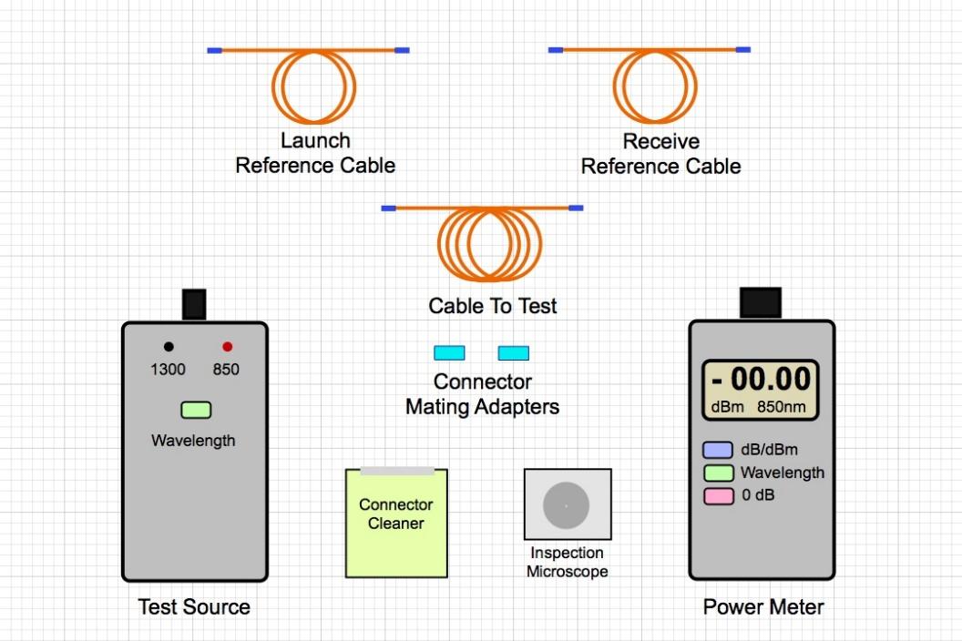
Figure 3: Insertion loss measurement tools
There are several techniques that can be used to measure insertion loss. One of the most common is the use of a network analyzer. This is a device that can measure the insertion loss of a device over a wide frequency range. Another technique is to use a signal generator and a power meter. This method is typically used to measure insertion loss at a specific frequency. Common insertion loss measurement tools are shown in Figure 3.
Insertion Loss Applications
Insertion Loss is a critical tool for any engineer working in the telecommunications and power industries. It measures the amount of power lost due to the insertion of two components, such as a filter or amplifier, into a transmission line. This concept is essential for engineers across multiple industries, including television and radio broadcasting, broadband communications, optical fiber systems, cellular networks, medical imaging scanners, and electric power distribution systems. Insertion loss is an important consideration in telecom and AV systems because it can have a significant impact on system performance. For example, if too much insertion loss occurs in a telecom system, it can result in dropped calls or poor call quality. In an AV system, excessive insertion loss can cause picture and sound degradation. There are many factors that contribute to insertion loss, including:
- Attenuation: The reduction in signal strength that occurs as a signal travels through a medium such as air, water, or fiber optic cable.
- Impedance mismatch: A condition that exists when the impedance of two components or systems connected together does not match. This mismatch can cause reflections that result in signal losses.
- Connector losses: The attenuation that occurs at the connection point between two components or systems. Poorly made connections can have high connector losses.
Insertion loss can also be used to compare two similar devices or systems quantitatively. For example, if two amplifiers have identical input and output impedance levels, but one has twice the insertion loss of the other, then the first amplifier is said to be twice as efficient as the second amplifier. In addition, insertion loss can be used to characterize the performance of filters, acoustic materials, and other devices. For instance, engineers may use insertion loss measurements to evaluate how well a filter eliminates certain frequencies from a signal or how much noise an acoustic material absorbs.


