The Ultimate Guide to FPGA Test Benches
15/12/2020, hardwarebee
Creating test benches for your FPGA design is a critical step for any FPGA design project. This article is written for the FPGA verification design engineers who want to use VHDL as HDL verification language for designing and simulating of their FPGA based digital design.
The VHDL test benches are used for the simulation and verification of FPGA designs. The verification is required to ensure that the design meets the timing requirements and is also used to simulate the functionality of the required specifications of the design.
Testbenches (test benches) are the primary means of verifications of the HDL designs. This article provides guidelines for constructing efficient test benches. How to write an efficient test bench that can cover all the corner cases, the testbench should be intelligent enough to verify the corresponding outputs meet the requirements. The testbench verification is important as it verifies your design functionality before putting it onto the real hardware.
Verification of the digital design is a cumbersome and time-consuming job, due to the nature of the FPGA hardware that requires to meet the timing requirements successfully to ensure the right functionality of the design. Before downloading the hardware design code into the FPGA it is a challenge for a verification engineer to write test benches that depicts the behavior of the hardware in the waveforms. Generally, verification engineers perform the following tasks through the testbench to ensure hardware functionality.
- Instantiate the design under test (DUT), basically a design for whom verification engineers require to write the testbench.
- Stimulate the DUT by applying test vectors to the model, generally, the verification engineer generates the pseudo-random number to cover all the test scenarios.
- Display the output results to a terminal and/or generate the waveform windows for visual perceptions, and use sometimes for debugging as well.
- Comparing actual results to expected results to conclude the design verification and requirements.
- Automatically provide a pass or fail indication.
The basic methodology of the test benches is to invoke the functionality of the design, then stimulate it by applying the different test vectors. The efficient test benches perform additional functions to ensure that the design meets all the requirements i.e., they contain logic to determine either the output of the underline testbench is the expected one or it deviates from the expecting results. The remaining article describes the structure of an efficient testbench, and provide an example of a self-checking testbench—one that automates the comparison of actual to expected testbench results.
The following figure shows the general architecture for the testbench. The testbench can provide the results either as the output values to the underlying verification software terminal e.g., Modelsim, test benches help to debug the design through digital waveforms, or we can also write the efficient test benches to make the automated verification with the predefined results store into the Database and results debugging.
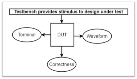
Figure 1: Testbench Verification flow
Testbenches can be written in VHDL or Verilog. Since test benches are used for simulation only, they are not limited by semantic constraints that apply to RTL language subsets used in synthesis. In short, Testbenches are independent of language and hardware constraints, providing a benefit to the verification engineer to use available behavioural constructs. Thus, test benches can be written more generically, making them easier to maintain.
Testbenches are easier to maintain as they are used to provide only the simulations results, make them independent from the semantic constraints, make them also independent from the synthesis workflow order. So, test benches can use all behavioural constructs.
The following sections are common VHDL testbench parts:
- Entity and Component Declaration
- Signal Declaration
- Port mapping of Top-Level Design
- Stimulus
Generating Clock Signals
The sequential logic must start with the generation of the clock signals. Iterative clocks can easily be implemented in VHDL. The following are VHDL code for clock generation:
| — Declare a clock period constant.
Constant ClockPeriod: TIME := 10 ns; — Clock Generation method 1: Clock <= not Clock after ClockPeriod / 2; — Clock Generation method 2: GENERATE_CLOCK: process Begin wait for (ClockPeriod / 2) Clock <= ’1’; wait for (ClockPeriod / 2) Clock <= ’0’; end process;
|
Generating Reset Signals
| — Declare a reset signal.
reset <= ‘1’, ‘0’ after T/2;
|
Automating the Verification of the Design through Testbench
Automatic verification of the test benches is recommended, usually for larger designs. Automation techniques that involve database comparison and self-checking reduce the time required to check a design to fulfill all the requirements, it helps for correctness need to be done, and minimizes debugging effort in the case of failure. Following methods are used for the automatic verification of the design through testbench.
- Database Comparison
- Waveform Comparison
- Self-checking Testbenches
Database Comparison
Database comparison based testbench verification consists of a database file containing the expected output (usually called a golden vector file). Verification engineer writes its testbench to generate the simulation outputs. The simulated outputs are captured/stored and compared to the golden vector file to ensure the working of the design. The only disadvantage associated with this method is the difficulty of tracing output to the provided golden vector file, that the golden reference file and generated output should align their timestamps. For example, the output pattern should follow the same timing delay provided in the golden vector file.
Waveform Comparison
Waveform comparisons can be performed automatically or manually. The automatic waveform comparison is not much in practice. Mostly, verification engineers generate the waveforms results and manually verified the results of the design with the expected outputs and draw their conclusion.
Self-Checking Testbenches
A self-checking testbench is a kind of intelligent testbench that checks actual results against the expected results at run time, not at the end of simulation like in the Database comparison. This technique is useful for error-tracking, it is helpful to make the error log, help to debug the design, debugging time is significantly shortened, helps to locate the error occurrence.
Example:
The stimulus can be generated with MATLAB or Python Script and testbench feeds it into design under test. The Design Under test generates the response and testbench stores it into a file. The results are compared through testbench to get the behavioral functionality of the design.
Test Bench Tips
Planning a good digital design helps to achieve a better circuit performance, planning a great testbench improves simulation time.
Know the simulator before writing the testbench
There are few HDL simulators available in the market e.g., Modelsim, Vivado, all these simulators comply with the HDL industrial standard. Different simulators have different features, capabilities, and performance characteristics, and produce different simulation results.
Event-based vs. cycle-based simulation
Simulators use event-based or cycle-based simulation methods. Event-based simulators trigger when an input, signal, or gate changes its value. In an event-based simulator, a delay value can be associated with gates and nets to achieve optimum timing simulation.
Cycle-based simulators target synchronous designs. These simulators analyze results at clock cycles. This feature makes cycle-based simulators faster and more memory efficient than event-based simulators.
Avoid using infinite loops
Infinite loops should not be used to provide design stimulus. Typically, clocks are specified inside an infinite loop (for example, “wait for” loops in VHDL).
Break up stimuli into logical blocks
In VHDL Process block works in parallel. The testbench stimulus becomes easier to implement and debug if independent stimuli are divided into separate blocks. In this case, each stimulus block works in parallel at simulation time zero. The use of separate stimulus blocks results in test benches that are easier to create, debug, maintain, and upgrade.
Modular Design
TB should be reusable without difficult modifications
- The structure of the TB should be simple enough so that other people understand its behaviour.
- It has to be easy to run – Not many dependencies on files or scripts.
- A good test bench propagates all the generics and constants into DUT.
Synthesizable Testbench
Writing synchronous, synthesizable test benches are a good practice if, e.g., the design includes clock domain crossings, to make it work on the FPGA. It is a good practice design that the testbench includes all the synthesizable constraints.
Timeout Counters
Use timeout counter to detect if the design does not respond at all! – You must not rely on the designer that checks the waveforms.
Random Test Input
Random test input is good for finding corner cases, they are easy to produce, allow large test vector sets. Use pseudo-random number generators to produce the same series if the seed is the same.
Assertion
It’s a good practice to use assertion, it is good for event detection, Checks the absence of a specific event, which is a sign of failure.
The basic syntax of a report statements in VHDL is:
report <message_string> [severity <severity_level>];
The message string has to be a string. The severity level has the datatype std. standard. severity level Possible values are note, warning, error, failure.
For example:
report “this is a message”; — severity note– or:report “this is a serious message” severity warning;
assert 5 = 2 + 2; assert 5 = 3 + 2 report “Assertion violation.”; assert 5 = 3 + 2 report “Assertion violation.” severity error;
VHDL Time Type
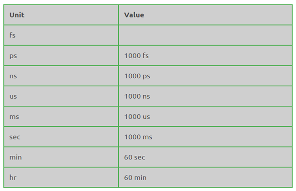
Try to use VHDL pre-defined Time Type. We need to define the time by providing a number and a time unit.
The table below shows the list of time units that we can use with the VHDL time type.
Real Life Example With Source Code
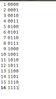
Consider the following example of the 4-bit counter, to do the verification of the counter we will consider the testbench verification.
Get the source code: Counter.vhd, Counter_tb.vhd.
Testbench verification of the counter with the help of Waves:
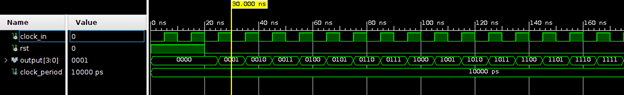
Testbench verification of the counter with the help of terminal output:
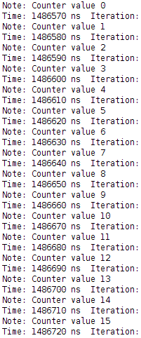
Testbench verification of the counter with the help of save the data onto the text file: