Types of Oscillators: Overview and Applications
13/06/2023, hardwarebee
Oscillators are electronic circuits that produce continuous periodic waveforms at the output without any external input signal. Oscillators are at the core of numerous applications, enabling the generation of radio waves, precise timing signals, audio frequencies, and much more. These versatile electronic circuits produce periodic waveforms with predetermined frequencies, forming the foundation for various functions, including timekeeping, communication, signal processing, and synchronization. Understanding oscillators and their operation is key to unlocking the true potential of electronic systems.
This article presents a comprehensive exploration of types of oscillators, covering their theoretical foundations, diverse types, and practical considerations. By delving into the intricacies of oscillators, engineers and enthusiasts gain the knowledge necessary to navigate the complexities of oscillator design and selection. As we unravel the mysteries of these mesmerizing electronic components, we unlock their rhythmic potential to drive the future of electronics.
Classifications
Oscillators can be broadly categorized into two groups:
- Feedback oscillators: RC oscillators, LC oscillators
- Relaxation oscillators
Feedback Oscillators
Feedback oscillators are also known as harmonic or linear or sinusoidal oscillators. They are based on an amplifier with positive feedback and the frequency of oscillations can be adjusted with the components in the feedback network. The frequency selective network can either be RC networks, LC tank circuits, or a crystal. A block diagram of an oscillator is shown below. It has an amplifier with gain A, and a feedback network having gain β. The output voltage VO of the amplifier is the input voltage of the feedback network. Similarly, the output of the feedback network is the input of the amplifier Vi.
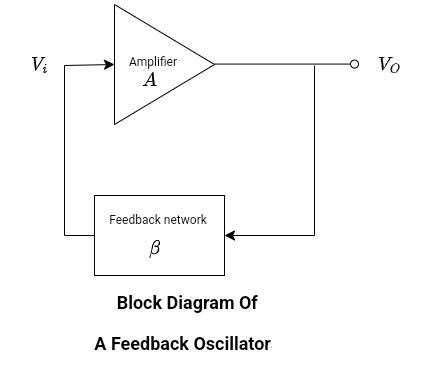
- The total phase shift around the loop must be 2π or N*2π. In other words, the input of the amplifier and the output of the amplifier are in phase with each other.
- The loop gain must be equal to unity. Aβ = 1.
Generally, oscillators with RC feedback known as RC oscillators are used for frequencies up to 1MHz.
Oscillators with RC feedback:
- Wein bridge oscillator
- Phase shift oscillator
- Twin T oscillators
Similarly, there are oscillators with LC networks in the feedback loop. Usually, these are used for a higher frequency of oscillations.
Oscillators with LC feedback:
- Colpitts oscillator
- Clapp oscillator
- Hartley oscillator
- Armstrong oscillator
- Crystal controlled oscillators
Wein Bridge Oscillators
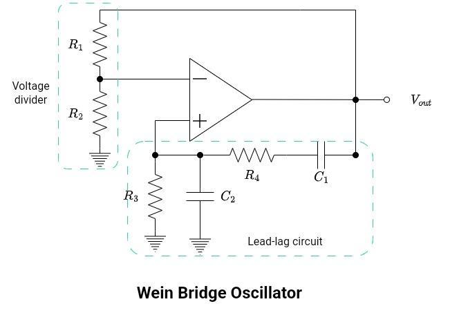
A Wein Bridge oscillator is a two-stage amplifier with an RC bridge network as the frequency-determining portion of the circuit. The amplification is provided by the op-amp, connected in a non-inverting configuration, resulting in a phase shift of 0°. The heart of the oscillator is the lead-lag circuit, which is connected in positive feedback to the op-amp. R1 and R2 collectively form a voltage divider, with their values determining the amplifier gain.
Its working is given below:
- Gain: The closed-loop gain of the amplifier is determined by the voltage divider.
- Start-up condition: The required minimum value of β for a Wein Bridge oscillator to start oscillating is approximately ⅓. To achieve start-up condition β exceeds the minimum required value of approximately ⅓.
- Frequency-determining network: It consists of a lead and lag circuit, connected in a bridge configuration consisting of R3, R4, C1, and C2. It acts as a resonant circuit.
- At very low frequencies, the series capacitor behaves as open to the incoming signal. The output approaches zero.
- As frequency increases, the output voltage approaches its maximum value. This frequency is known as the resonant frequency. At this frequency, the phase shift across the loop is 0°.
- Similarly, at very high frequencies, the shunt capacitor acts like a short. And hence again there is no output.
- Resonant frequency determination: This frequency is determined by the values of capacitors and resistors in the bridge. Consider C1=C2=C and R3=R4=R.
- Applications: They are suitable for low frequencies. Therefore, they are used in audio frequency signals for various purposes, such as audio testing, musical instrument synthesis, and audio effects processing.
RC Phase Shift Oscillators
The RC phase shift oscillator consists of an op-amp as an amplifier, whose output is 180° out of phase. It utilizes three-stage RC networks.
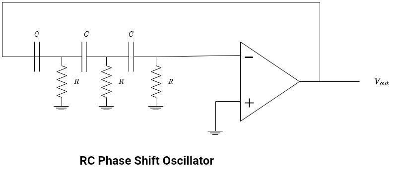
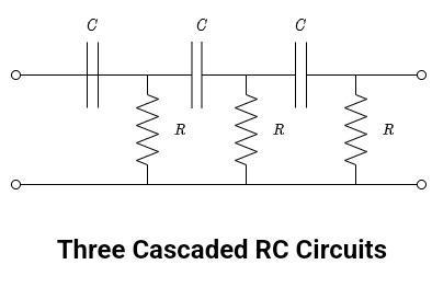
As observed from the schematic diagram, the circuit comprises three RC circuits (or filters) connected in a cascade. Each RC filter provides a maximum phase shift of 90°. By selecting suitable values of resistance (R) and capacitance (C) such that each RC network produces a phase shift of 60° at the desired frequency, a total phase shift of 180° is achieved. The use of three filters enhances frequency stability.
- Gain: The gain of the amplifier is set to 29 to meet the Barkhausen criterion for oscillations.
- Start-up condition: The required minimum value of β for a phase shift oscillator to start oscillating is approximately 1/29. To achieve the start-up condition, β must exceed this minimum value. At a certain frequency, when Aβ > 1, the oscillations can begin.
- Frequency-determining network: It consists of three lead circuits in the feedback path.
- Resonant frequency determination: This value is set by the capacitor and resistors in the feedback network.
Suppose R1 = R2 = R3 =R, and C1 = C2 = C3 = C. Then the generalized expression for the frequency of oscillations produced by an RC phase-shift oscillator is given by
Where,
R is the feedback resistor
C is the feedback capacitor
N is the number of RC stages
Applications: This oscillator is utilized for the generation of stable and precise sinusoidal signals over a wide range of frequencies. It includes audio frequency signal generation, frequency synthesis, and waveform generation. It is also used in communication system applications for signal processing, such as modulation, demodulation, frequency mixing, and PLL.
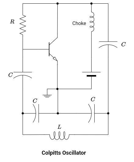
Colpitts Oscillators
It can be implemented with a number of active devices like BJT, FET, and operational amplifiers. The feedback network contains an LC-tuned circuit, which acts as a bandpass filter. As discussed earlier, oscillators with LC feedback networks are used for higher-frequency applications.
Gain:
Start-up condition:
The required minimum value of β for a Colpitts oscillator to start oscillating is approximately C1/C2. To achieve the start-up condition, β exceeds the minimum required value. At some frequency Aβ>1, then oscillations can start.
Frequency-determining network: It includes the LC-tuned network. The frequency of oscillations is controlled by this bandpass filter. The inductor L is in parallel with two series capacitors, C1 and C2. C1 and C2 collectively form a capacitive voltage divider. It provides the necessary phase shift for oscillations.
Resonant frequency determination: The frequency of oscillations is set by C1, C2, and L.
Applications:
- It is a feedback oscillator and is used to produce high-frequency sinusoidal waveforms.
- It is used in the generation of radio frequency signals
- Colpitts oscillators are commonly employed as local oscillators in radio frequency receivers.
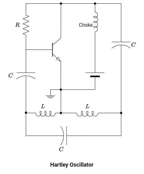
Hartley Oscillators
Hartley’s oscillator is similar to the Colpitts oscillator; they are electrical duals of each other. In the Hartley oscillator, the feedback network contains two series inductors and a parallel capacitor.
- Gain: The gain and attention factor (β) is similar to the Colpitts oscillator.
- Start-up condition: Like in the Colpitts oscillator, to commence oscillations, the product of the (A) and β at a certain frequency exceeds 1 (Aβ>1).
- Frequency-determining network: It also includes the same LC-tuned network. The frequency of oscillations is controlled by this bandpass filter. It has a capacitor C in parallel with two series inductors L1 and L2. This network provides the necessary phase shift for oscillations.
- Resonant frequency determination: Here the frequency of oscillations is set by C1, C2, and L.
- Applications: The Hartley oscillator has similar applications to that of the Colpitts oscillator, it can be used as a building block of many electronic circuits like PLL (phase-locked loop), VCO (voltage-controlled oscillators), and clock generation circuits.
Relaxation Oscillators
The other type of oscillator is known as a relaxation oscillator. The frequency of oscillations is controlled by the timing constant of the RC network.
They produce non-sinusoidal waveforms like triangle, square, and saw-tooth waveforms. Its operation is based on the charging and discharging of the capacitor.
Some well-known relaxation oscillators are given below:
- Triangular wave oscillator
- Square wave oscillator
Square Wave Oscillators | Generators
Schmitt trigger oscillators are the simplest waveform generator circuits. The square wave signal is characterized by high and low voltage levels., The circuit consists of a feedback resistor and a capacitor. The oscillation frequency is dependent on the values of R and C. The oscillations are created by the charging and discharging of the capacitor. The value of R is set to be very high, and hence, the circuit has a very high voltage gain.
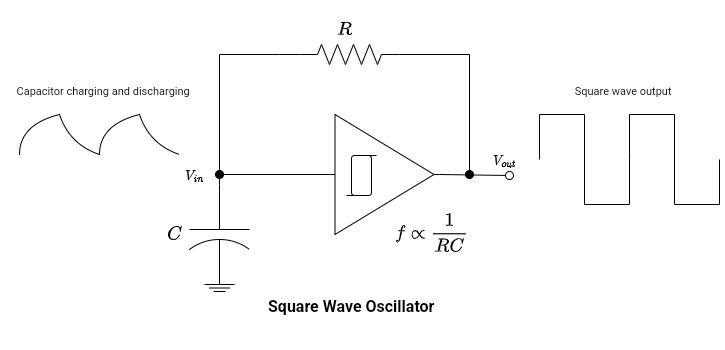
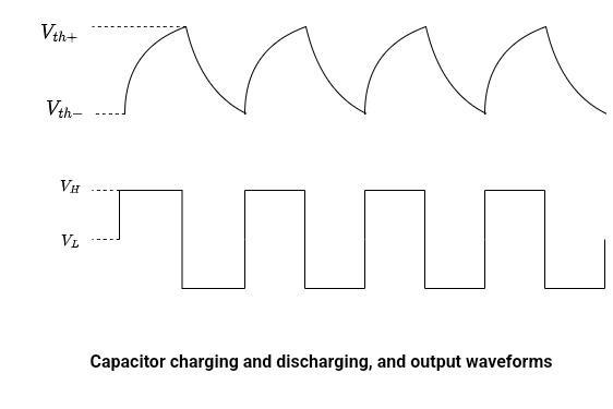
- Initially, the capacitor starts to charge from Vth- to Vth+.
- Look at waveforms, when the capacitor charging is at Vth-, the oscillator output is high, that is VH.
- As the capacitor charges up to Vth+, the output quickly goes low, which is VL.
- The capacitor starts to discharge and reaches the lower threshold value Vth-.
- Again the output switches its state from VL to VH.
- The same process repeats.
Applications:
- Commonly found in digital systems and digital signal processing. They are used as clock generators and timing circuits for synchronizing digital circuits.
- Used in PWM. By adjusting the duty cycle of the square wave PWM signals can be generated.
- Used in switching power supplies for controlling the operation of power transistors.
Triangular Wave Oscillators | Generators
The circuit diagram has two operational amplifiers, where one functions as a Schmitt trigger and the other as an integrator. The Schmitt trigger generates a rectangular wave output, which is then used as the input for the next op amp which is an integrator. The integrator produces a triangular wave output. This triangular wave is then fed back to the input of the Schmitt trigger, creating a positive feedback loop. This arrangement enables the first stage to drive the second stage, and vice versa.
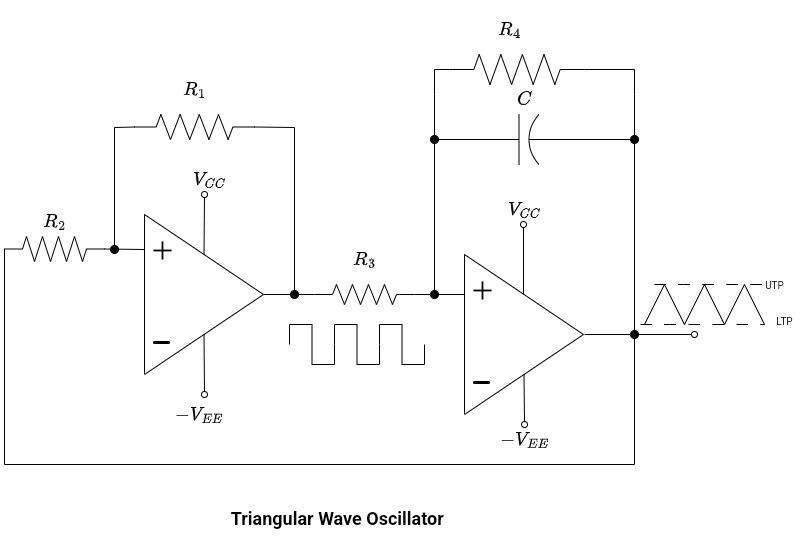
The Schmitt trigger operates in two distinct states. Both of them are level sensitive. Hence, the output switches between these two states.
When the output of the Schmitt trigger is low, a positive ramp occurs at the output of the integrator. This ramp signal is then fed back to the Schmitt trigger, causing the ramp signal to increase until it reaches the upper threshold value (UTP). At this point, the output of the Schmitt trigger goes high, causing the integrator waveform to change its direction. Now, the output of the integrator becomes a negative ramp. This negative ramp is fed back to the input of the first op-amp. As the negative ramp reaches the lower threshold value (LTP), the output of the Schmitt trigger goes low.
Applications:
- It works as a part of PWM circuits.
- They are part of function generators.
- They are the core component of VCOs.