
Understanding Wheatstone Bridge
08/05/2022, hardwarebee
Wheatstone bridge is one of the most well-known measuring systems that measure the unknown resistances precisely. For this reason, the Wheatstone bridge is known as the resistance bridge. Moreover, this bridge can be used for measuring instrument calibration, i.e., voltmeter or amperemeter. In this article, this useful measuring system is explained comprehensively together with its applications.
The Wheatstone bridge is an electric circuit that includes four resistive arms. Samuel Hunter Christie invented this bridge in 1833, and then Sir Charles Wheatstone developed and popularized it in 1843. The name of the bridge has been adapted from Sir Charles Wheatstone. Nowadays, resistances can be measured by ohm- or multi-meters, but the Wheatstone bridge is also used for accurate measurement of very small resistances in the range of milli-ohms or less. Among the resistances, two of them are known, one is them is variable resistance, and the last one is an unknown resistance. The fundamental idea behind this circuit is simple, and it is based on a balanced condition. Figure 1 illustrates the Wheatstone bridge configuration and its parameters that will be used throughout the article, including four resistances (R1, R2, R3, and R4), one ampere or voltage meter, and one DC voltage source like a battery. In this configuration, the voltmeter or amperemeter is connected in between resistor arms (nodes C and D), as shown in the figure. It should be noted that the meter must be connected the same as the figure, and other connections do not create the Wheatstone bridge, and the equations are invalid for them.
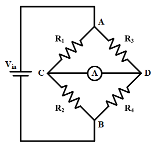
Figure 1: Schematic circuit of the Wheatstone bridge including four resistive arms
Before presenting the measuring concept, the Wheatstone bridge equations are proposed. At first, an amperemeter is considered between nodes C and D. In the balancing condition, no current flows through the meter. It means the voltage between the meter terminals. Therefore, the following equation can be written.
(1)
![]()
In this situation, the Wheatstone bridge circuit can be converted to the circuit, shown in Figure 2. The current flowing through is going through because the amperemeter shows zero current. Similarly, the current in and are identical.
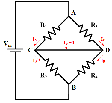
Figure 2: Current flow in the Wheatstone bridge circuit by considering the balanced condition (measurement instrument current equal to zero).
Since nodes C and D have an equal voltage, the voltage across R1 and R3 is the same. Thus, it can be written:
(2)
![]()
Similarly, the voltage across the other resistances is equal. Therefore:
(3)
![]()
By Equations 2 and 3, the following equation is obtained.
(4)
![]()
According to Ohm’s low, the voltages are a product of current and resistance, and Equation 4 can be modified to:
(5)
![]()
Finally, by simplifying the previous equation, the next equation is achieved.
or
(6)
![]()
The Wheatstone bridge can also be built by using a voltmeter instead of an amperemeter. In this situation, the middle branch would be open-circuited because the voltmeter has a high impedance. In other words, no current is flowing through the middle branch. If the measured voltage is zero, the bridge will be in a balanced condition, and the explained ratios between resistances are valid. The presented results are valid for other configurations with more than four resistances. As can be seen in Figure 3, two resistive arms have been added to the circuit, and two amperemeters are available in the middle branches.
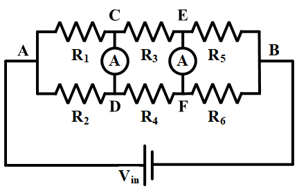
Figure 3: Extended series Wheatstone bridge configuration
In a balanced condition, no current flows through the meters, and all aforementioned equations can be written for this circuit. Since the currents are zero in amperemeters in a balanced condition, voltages in nodes C and D are equal, and nodes E and F have similar voltages. Thus:
(7)
![]()
and it can be concluded that the ratio between resistances in following equation are still valid.
(8)
![]()
This configuration can be extended more, and in a balanced condition, the ratios are valid. There is also another extended Wheatstone configuration with more than four resistances which is shown in Figure 4. In this case, the current in the middle branches must be zero to have a balanced condition. According to the presented procedure, the voltages across R1, R2, and R5 are equal.
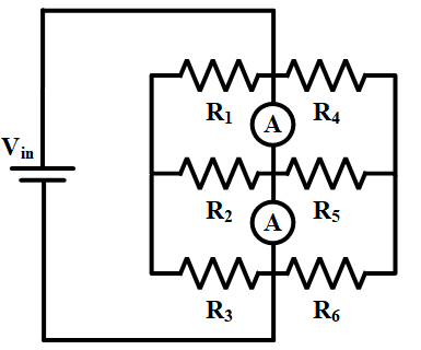
Figure 4: Extended parallel Wheatstone bridge configuration
Moreover, other resistances have similar condition, and their voltages are equal. Therefore, it can be written:
(9)
![]()
and
(10)
![]()
It means that equation 8 is also valid for parallel configuration.
Now, the whole concept is clear, and the application of this bridge is introduced in the following parts. As mentioned before, the Wheatstone bridge is mostly used for measuring the resistance value of an unknown resistor in an accurate way, especially when the resistance is considerably small. For the presented purpose, the unknown resistor must be placed in one arm, and a variable resistance must be in another arm. Two other resistances are constant. The schematic circuit is illustrated in Figure 5, where Rx is unknown resistance and Rv is a rheostat or variable resistance. The procedure has been explained before, and finding a balanced condition is the only thing that is needed. To find the balanced point, the amperemeter must be monitored when the rheostat changes from zero to the maximum value. Once the amperemeter shows zero current, the adjusted resistance of the rheostat should be recorded. In this stage, three resistances are known, and the unknown resistance can be found by equation 6, as below:
or
(11)
![]()
In a practical situation, the unknown resistance range should be identified due to high accuracy. When all resistances are in the same resistance range, the measurement will be precise.
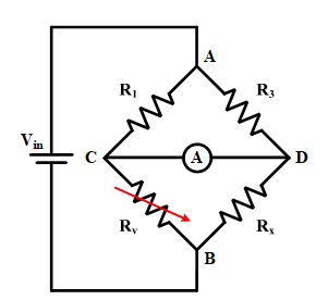
Figure 5: The Wheatstone bridge configuration for measuring an unknown resistance
After explaining the principle of the Wheatstone bridge, its applications and limitations will be discussed. The main application of this bridge is to measure the low resistance values accurately, but its application is not limited to resistance measurement. It can also be used for measuring physical parameters like strain or pressure, light, and temperature. Theoretically, this bridge can measure any impedances, including inductances and capacitances. However, using a variable capacitor or inductor for adjusting the bridge in a balanced condition is not as easy as a variable resistor. As an example, strain measurement is introduced in this article.
Although the Wheatstone bridge can be used for precise measurement, some parameters impact its accuracy and create an error in measurement. For instance, in low resistances, the resistance of contacts and leads affects the bridge balancing condition, and their resistances should be considered in calculations that are difficult in some cases. Furthermore, flowing current through the resistances produces heat which changes the resistance values.
A common application of the Wheatstone bridge is strain measurement. The strain gauge is used to measure the strain on an object which was invented by Edward Simmons and Arthur Ruge in 1938. In fact, mechanical factors such as pressure, force, or strain are presented by electrical resistance variation. Therefore, the gauge resistance can represent the mechanical parameters, and accurate measurement of resistance will lead to accurate strain measurement. For this purpose, the strain gauge must be located on one bridge arm as an unknown resistance, and the variable resistance can adjust the bridge into a balanced condition.
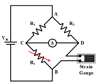
Figure 6: Strain gauge resistance measurement
The strain gauge in the Wheatstone bridge is shown in Figure 6. In some cases, using variable resistance is hard, and an unbalanced Wheatstone bridge can be utilized. In an unbalanced condition, mechanical parameters will have a linear proportion with the measured voltage at the middle nodes.
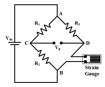
Figure 7: A sample of unbalanced Wheatstone bridge
In this condition changing the mechanical parameters will exit the bridge from the balanced condition, and nodes voltages can be obtained by Equations 13 and 14.
(13)
![]()
(14)
![]()
Therefore, Vg would be equal to:
(15)
![]()
It means the strain resistance can be measured by having Vg.
All in all, the Wheatstone bridge has been explained comprehensively, and its application has been defined with some examples in balanced and unbalanced conditions. Moreover, some limitations have been presented in this article.


