Working Principle of a Transformer
18/05/2022, hardwarebee
The transformer is one of the most important equipment in electrical engineering, which changes the magnitude and phase angle of AC input. In fact, the transformer is a static electrical machine because there is no rotating part in the transformer. Moreover, the transformer is a passive component that transfers energy from one side to the other side. As mentioned before, this device works with AC input, and transferring DC input is not possible by the transformer. In this article, working principle of a transformer are discussed completely, including the theory of magnetic conversion, equivalent circuits, different types of magnetic core, and transformer applications.
Transformer Working Principle
The transformer has two main parts, a including magnetic core and two or more windings. The AC source is applied to one winding as an input, and the output voltage is obtained from the other one, as shown in Figure 1. The windings are mostly made of copper or aluminum because of their acceptable conductivity. In fact, the conductors are wrapped around the magnetic core to produce a magnetic field in the transformer core. In most cases, the magnetic core is also made of ferromagnetic materials, i.e., iron. However, diamagnetic or non-magnetic materials, such as air, wood, and plastic, are used for some special purposes.
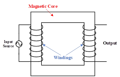
Figure 1: Different parts of a sample two-winding transformer, including magnetic core and windings.
When a transformer coil is connected to an AC voltage source, an alternating magnetic field is generated around the coil, as shown in Figure 2. This magnetic field produces magnetic flux, which traverses through the core to close its path. However, a fraction of the magnetic flux tends to close its path in a shorter path, which means a path in the vicinity of the coil, namely stray flux. The magnitude of generated flux is proportional to the magnitude of current flowing through the coil, and the flux direction is based on the current direction in the winding, which can be obtained by the right-hand rule. This rule expresses that when fingers are curled into a half-circle around the wire in the direction of the current, the thumb shows the magnetic flux direction. In an ideal condition, the stray flux is zero, and all generated fluxes traverse through the magnetic core. When a magnetic flux passes through a coil, a voltage is generated at the coil’s terminals which is the most important concept of the transformer. Therefore, when the core flux passes through the secondary winding in the following figure, a voltage will be generated at its terminals. In this way, the input power is transferred from the primary winding to the secondary winding without any electric connection. In fact, the power is transferred magnetically and by the magnetic core. Thus, it is said that the voltage is induced to the secondary. The magnitude of the induced voltage in secondary winding has a direct relation to the winding turns number which can be defined at the design stage.
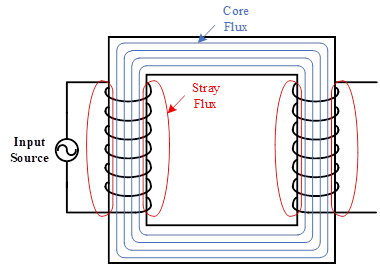
Figure 2: Various fluxes in a single-phase transformer
Shell-type vs. Core-type
Before discussing the transformer equivalent electrical circuit, different types of transformer cores are presented in Figure 3. As can be seen, in the shell-type transformer core, the winding is surrounded by the core, but the core-type is different in which transformer core is surrounded by the winding. To get the maximum magnetic coupling, in core-type design, the windings are interleaved and concentrated. It means that the LV winding in a core-type design is located near the core, and then HV winding is wrapped around the LV winding (HV winding surrounds the LV winding). There are some reasons for this winding configuration. The first reason is that the LV winding has the lower voltage, and less insulation is required to separate the LV winding from the grounded core. Moreover, as the higher current flows through the LV winding, locating this winding in the vicinity of the core produces lower losses due to lower resistance and the average length of winding. However, the winding configuration in shell-type design is different, and it is called sandwich windings configuration. In this configuration, the HV and LV windings are located on top of each other, which is similar to making a sandwich. The configuration scheme is presented in Figure 3. Thus, despite the winding configuration in core-type design, both LV and HV windings are wrapped around the core with appropriate insulations between windings and transformer core.
At the same voltage, the shell-type design needs more insulation because the HV winding must be insulated from the core. However, in a core-type design, only LV winding must be insulated from the core, which needs fewer insulations. Therefore, for high voltage and low power applications, a core-type design is preferred. Inversely, the shell-type design is used for high power and low voltage transformers. Furthermore, the cooling is more effective in core-type design. Finally, as mentioned before, in shell-type design, the winding is surrounded by the core, which can protect the winding against mechanical forces.
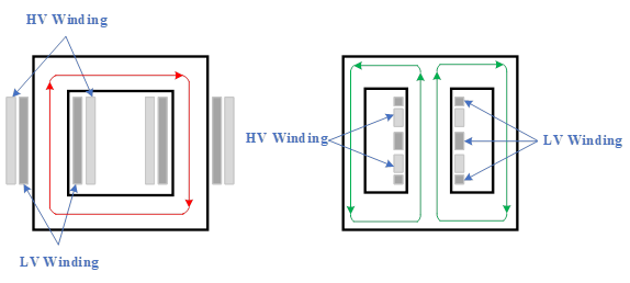
Figure 3: Different types of transformer core: core type (left) and sell type (right)
Transformer Parameters
In the transformer, the primary and secondary powers are equal, and the following equation can be written as given:
(1)
![]()
When the primary winding is connected to a time-varying voltage, a time-varying flux Φ is
established in the core. The induced voltage will be equal to the applied voltage if the resistance of the winding is neglected, and based on Faraday’s law, the primary voltage (V1) can be achieved by:
(2)
![]()
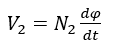
Similarly, the induced voltage in the secondary winding can be obtained as:
(3)
Therefore, the following equation can be used for an ideal transformer as:
(4)
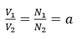
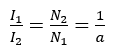
which means that the primary and secondary voltages are proportional to the transformer turns number ratio. Moreover, according to Equation 1, the primary and secondary currents are also proportional to the transformer turns ratio as:
(5)
After understanding the transformer windings voltages and currents, impedance is another important parameter that must be investigated on each side of the transformer. When a transformer is connected to an impedance like a load, and a voltage is applied to the primary side, load impedance can be written as:
(6)

Similarly, the impedance from the primary side would be:
(7)

Therefore, the input impedance can be modified based on Equations 4, 5 and 6, as:
(8)
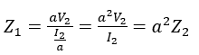
This equation is useful when an impedance needs to be transferred to the other side of the transformer for simpler calculations.
Practical Transformer Equivalent Circuit
In an ideal transformer, the transformer resistances are negligible, the stray or leakage fluxes are zero, and the excitation current for creating flux in the core is also negligible. However, these assumptions are not correct for real transformers. Hence, the neglected parameters are investigated in the following sections. In Figure 4, an equivalent circuit of a practical transformer is shown. In fact, a practical transformer consists of an ideal transformer, primary and secondary windings resistances, and leakage inductances on each side of the transformer. The transformer ratio is .
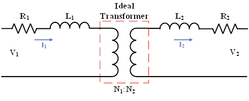
Figure 4: Equivalent circuit for a practical transformer
However, in Figure 4, the core effect has not been considered, and the equivalent circuit can be modified by adding a parallel branch to the presented equivalent circuit. In a practical magnetic core having finite permeability, a magnetizing current is required to establish flux in the core. This effect can be represented by a magnetizing inductance . Also, the core loss in the magnetic material can be represented by a resistance .
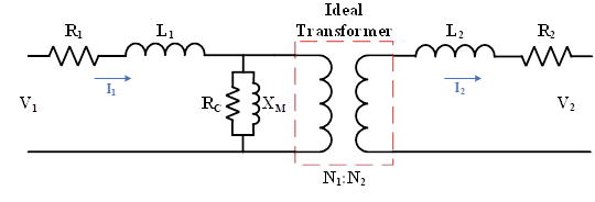
Figure 5: Modified equivalent circuit for a practical transformer
Transformer Efficiency
The transformer is one of the most efficient equipment because there is no rotation part in it to increase the losses. Interestingly, a well-designed transformer has around 99 percent efficiency. The efficiency can be calculated as:
(9)
where the input power is a combination of output power and losses. Hence, different types of transformer losses are defined as winding and core losses. Therefore, the efficiency can be re-written as below:
(10)
The winding losses are due to winding resistances. Core losses include eddy and hysteresis losses.
Autotransformers
In a transformer, the windings are electrically isolated, and windings are coupled magnetically. However, there is a special connection of the transformer, which is named autotransformer. In this type of transformer, a variable AC voltage can be obtained at the secondary. In contrast to the two-winding transformer discussed earlier, the primary and secondary of an autotransformer are physically connected. However, the basic principle of operation is the same as that of the two-winding transformer.
As can be seen in Figure 6, the autotransformer is similar to the transformer, and the voltage ratio is equal to the turns ratio, which means that Equation 4 is valid for an autotransformer. Moreover, Equation 5 can also be used for autotransformers. The only difference is that the secondary voltage is a fraction of the primary winding in a step-down autotransformer, and the secondary winding terminal can sweep over the primary winding to produce variable voltage. The advantages of an autotransformer connection are lower leakage reactances, lower losses, lower exciting current, increased kVA rating, and variable output voltage when a sliding contact is used for the secondary. The disadvantage is the direct connection between the primary and secondary sides.
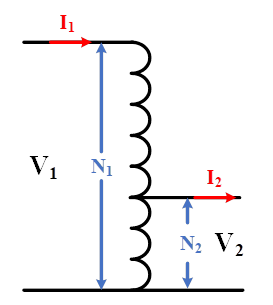
Figure 6: A sample step-down autotransformer
Transformer Applications
It can be said that the transformer is used for all devices and has a wide range of applications. For instance, a power transformer is one of the most important apparatuses in a power system that changes voltage levels. Another application is in electronics such as rectifiers, inverters, and other converters. Another application of a transformer is for insulation. In this application, the transformer turns ratio is mostly one because the only duty of this type of transformer is to electrically separate the primary and secondary circuits. The transformer is also used to measure AC currents and voltages, which are called current transformer (CT) and voltage transformer (VT), respectively. Apart from the mentioned applications, high-frequency transformers can be used to supply the X-ray. All in all, the transformer is available wherever an AC voltage is available.