
The Ultimate Guide to Ring Oscillators
01/03/2022, hardwarebee
In this article we will discuss the ring oscillator, which is one of the most popular circuit topologies in the digital world. Ring oscillators provide a wide tuning range, a small footprint, and multiple phase outputs. We will talk about the basic concepts of ring oscillators, the functional description of the ring oscillator, the different topologies that can be applied, and the many applications of the circuit.
Oscillators are among the most important and versatile structures in electronics. From audio synthesizers to lock-in amplifiers, they play a fundamental role in signal generation, waveform synthesizing, and timers. In digital systems, oscillators are responsible for producing the heart of sequential circuits: the clock. The clock signal allows the circuit to perform sequential operations and gives it the ability to precisely set the time of important events. Therefore, it is impossible to design digital processing circuits without oscillators. There are many types of oscillators described in the literature, such as resonance oscillators and crystal-based oscillators.
Basic Principles of Oscillators
In general, the main objective of an oscillator is to generate a voltage or current signal at a specific frequency. To achieve this goal, the circuit consists of a positive and unstable feedback network. There are two main types of oscillatory circuits: resonant linear oscillators and relaxation oscillators. Resonance oscillators use an LC tank in the feedback path of a linear circuit to provide positive feedback at a specific frequency (Figure 1). Crystal-based oscillators, which also fall into the category of resonant circuits, replace the LC circuit with a crystal with a stable resonant frequency. These circuits are designed to follow the Barkhausen oscillation criterion, which states that the loop gain must be equal to 1 and the phase shift around the loop equal to 2π to sustain oscillatory regime at the desired frequency.
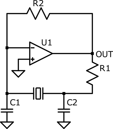
Figure 1: Resonant Oscillator using a crystal
Relaxation oscillators, on the other hand, use non-linear devices to create an unstable network. The principle consists of using switching devices, such as comparators, op-amps, and transistors, to charge a reactive device (capacitor or inductor) until the voltage level reaches an upper-level threshold. When the threshold is reached, the reactive device is discharged down to the lower-level threshold, after which the circuit switches back to the initial state, and the process repeats. The amplitude and frequency of relaxation oscillators are defined by the time constants of the charging/discharging networks and the threshold levels of the switching devices. Because it is possible to use different time constants and thresholds for the charging and discharging states, relaxation oscillators can generate asymmetrical waveforms with different shapes. The most popular relaxation oscillator is the astable multivibrator, shown in Figure 2.
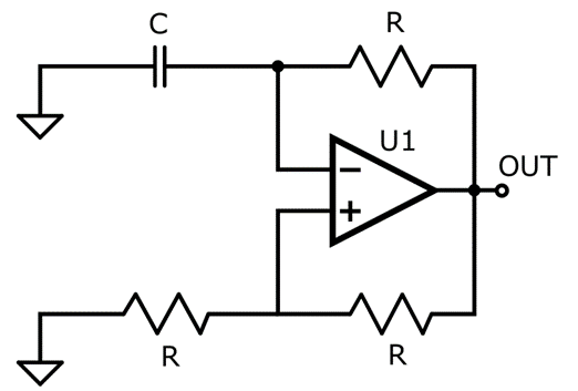
Figure 2: Relaxation Oscillators
The Ring Oscillator
The ring oscillator is one of the most simple, effective, and reliable oscillatory topologies, and it is widely implemented in the industry. The circuit functioning principle is similar to relaxation oscillators, although the technical literature often treats them as different things. It consists of an odd number of inverters, or NOT ports, in series, with the output signal of the last inverter being fed back to the input of the first inverter. The circuit can be seen in Figure 3, in a generic implementation using three NOT ports.
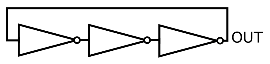
Figure 3: Ring Oscillator with three stages
The first principle of the ring oscillator is logical instability. By looking at Figure 4, we can see that the signal is being inverted by the first NOT port, so the output of the second is equal to . The process repeats in the second and third inverter, resulting in an overall output signal equal to . By feeding back this signal to the input, it becomes a combinatory contradiction, as , so the circuit is logically unstable.
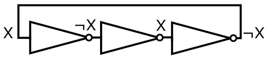
Figure 4: Logical Instability
The second principle of the ring oscillator is the delay introduced by the inverters, which is defined by RC circuits at the output of each stage. This means that the output of the inverter will take seconds to update the value after the input changes, so the circuit can hold the logical contradiction for a period of time. The delay of each inverter is calculated as the time needed to charge (and discharge) the capacitor up (and down) to the inverter logical threshold. The circuit with the RC networks can be seen in Figure 5.
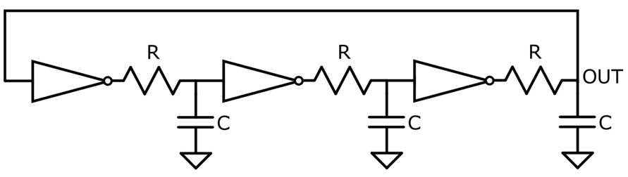
Figure 5: Three-stages ring oscillator with RC networks
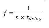
In practical applications, each inverter is designed to be identical, so the time constants, thresholds and amplitudes are all the same. This means that the frequency of the output signal is a function of the delay time and the number of inverters . Therefore, the oscillation frequency can be controlled by changing either the Tdelay or the number of cascaded inverters.
Simulations
To better understand the functioning of the circuit, we simulated a simple ring oscillator with three inverter stages. The inverters were implemented using push-pull CMOS circuits, and each stage were followed by an RC series of C = 10 pF and R = 1.0 kΩ. The circuit is shown in Figure 6.
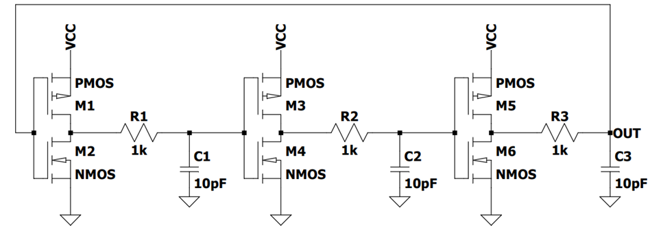
Figure 6: Three-stages ring oscillator based on CMOS inverters
By running a transient simulation on LTSpice, we get the signal shown in Figure 7. It can be seen that the output goes almost rail-to-rail, with amplitude of approximately 4.4 V peak-to-peak. Moreover, the waveform is almost a sine function, with a frequency of around 888 kHz. This means that the inverter delay is approximately 375.38 ns.
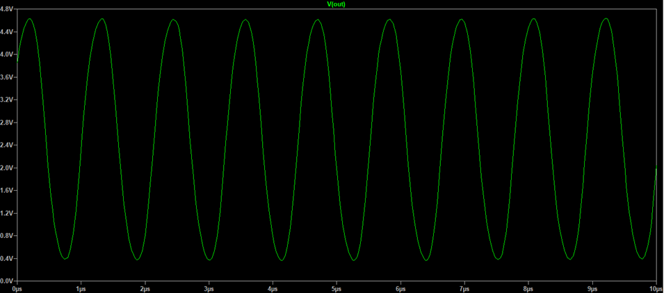
Figure 7: Output Signal of the Three-stages ring oscillator
Furthermore, by taking the signals at each inverter output, we can see that they are 2π/n radians out of phase, which is equal to 120° for n = 3. This is confirmed by the simulation in Figure 8, which shows the output of each stage with a 120° phase step between them.
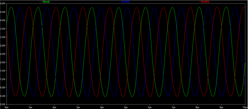
Figure 8: Output signal of each stage
As discussed previously, the frequency of the ring oscillator can be defined by the number of inverter stages. However, it is important to ensure that the number of inverters is odd, so that the combinatory logic remains unstable. By adding two new stages to the ring oscillator, we get the circuit shown in Figure 9.
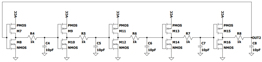
Figure 9: Five-stages ring oscillator
The output signal of the five-stages ring oscillator is shown in Figure 10. Due to saturation, the waveform is significantly more distorted than in the three-stages case, so the frequency content is less pure. Also, the frequency is equal to 510.5 kHz, which is approximately 0.57 times lower than the three-stages case. This is close to the 3/5 ratio of the number of stages, that is expected from the previous discussion.
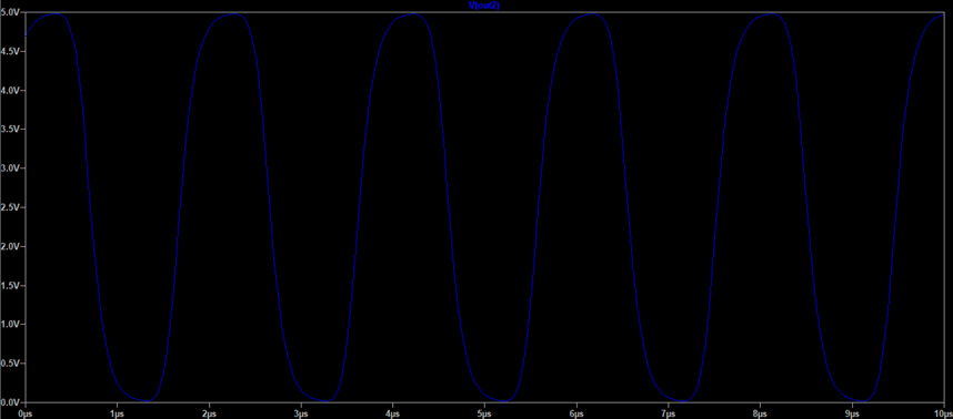
Figure 10: Output Signal of the five-stages ring oscillator
Pros and Cons
The ring oscillator is an incredibly simple and straightforward circuit to design and implement, which makes it perfect for a variety of devices and situations. However, there are several limitations that makes it prohibitive in some critical applications, especially the ones requiring stable and jitter-free timings. In this section, we will discuss the main advantages and disadvantages of the ring oscillator.
Pros
When compared to resonating oscillators, the ring topology offers much smaller footprint, as it does not require the use of LC tanks or crystals. Therefore, ring oscillators are a great choice in on-chip applications with critical limitations in terms of area. Also, the frequency content of ring oscillators is significantly purer than relaxation-based circuits, with the power being focused on the fundamental harmonic. Furthermore, ring oscillators are incredibly simple to understand and design, with the frequency being easily tuned with the number of inverter stages. Finally, ring-oscillators can be designed for low power consumption.
Cons
One of the main disadvantages of single-ended ring oscillators is the absence of voltage control, which prohibits its application in systems requiring variation of frequency. Moreover, these ring oscillators are too dependent on the supply voltage, which may cause jitter and frequency deviations if the supply is not stable enough. One solution for both problems is the use of differential inverters, which comes with the advantage of increased noise immunity. Ring-oscillators are also highly dependent on the temperature of the chip, which is not desirable if highly precise frequencies are required. Finally, ring oscillators are known for having worst phase noise and jitter performance than resonant oscillators.
Ring Oscillator Applications
Ring oscillators are very versatile circuits, with several applications in the industry. The first major application is in phase-locked-loops (PLL), where ring oscillators are often used as the main voltage-controlled oscillator (VCO). PLLs are crucial components in digital systems, applicable in signal demodulation, clock recovery and frequency multipliers. Ring oscillators are also widely applied in testing, including verification of manufacturing effects and new technologies. Furthermore, the intrinsic jitter of this type of oscillator can be used in the generation of random number sequences. Finally, ring oscillators can be applied used as temperature sensors, as the frequency can change significantly with the chip temperature.


