
Understanding Transimpedance Amplifier
14/05/2022, hardwarebee
Weak signals cannot be measured with high accuracy because measurement instruments need high accurate elements, which increases the costs considerably. Therefore, the sensors’ output must be amplified, and then other conversions and measurements can be applied. Some sensors’ outputs are based on current, and their amplitudes are quite low. Hence, the current must be converted to the voltage for measurement and then becomes amplified for more accuracy in the measuring process. As can be seen, the measurement process needs an I-V converter to convert the sensors’ current output to the voltage, and then the voltage is measured in a data acquisition unit. In this article, the converter unit is discussed comprehensively as a transimpedance amplifier (TIA) is a current to voltage converter.
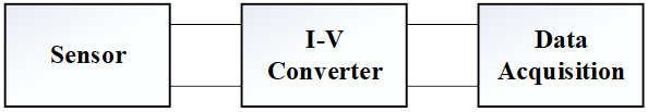
Figure 1: Schematic of a measuring process
The converter can be a current-controlled voltage source as the output voltage can change by controlling the input current. The simplest type of current to voltage converter uses a resistance together with a current source, as shown in Figure 2. In this circuit, the current source flows through the circuit and produces a voltage across the resistance, which can be determined based on Ohm’s law. It means that the resistor voltage can be changed by varying the source current when the resistance is constant. The important problem in this circuit is the load effect. If a parallel load resistance is added to the circuit, the equivalent resistance must be calculated, and the results become completely different depending on load resistance. When the load resistance is significantly greater than the circuit resistance, the load effect will be at the minimum point. Thus, the resistive circuit cannot satisfy the requirements of a useful current to voltage converter.
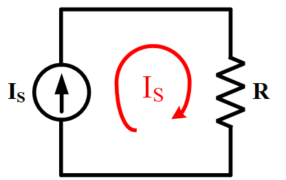
Figure 2: A simple current to voltage converter by a resistor load and a current source
To overcome the mentioned problem, an active converter by using op-amp is explained in this article. A simple converter consists of an op-amp, a current-based sensor, and a feedback resistor, as depicted in Figure 3. In this configuration, the non-inverting terminal (positive) is grounded, and the inverting one (negative) is connected to the sensor. There is also a feedback connection between the negative terminal and the op-amp output. Owing to the virtual ground concept in op-amps, the voltage of inverting terminal would be equal to zero.
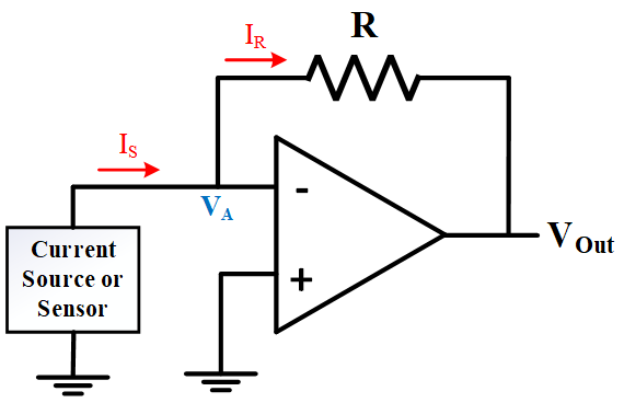
Figure 3: Active current to voltage converter using op-amp with feedback
In fact, this concept expresses that a node of the op-amp circuit is at a steady reference potential without being directly connected to the reference potential. Therefore, it can be written that is equal to zero. In addition to this feature, the op-amp has a high-impedance input, and no current flows through the terminals. Hence, the source current and the feedback current are approximately equal, and it can be written as:
(1)

By writing Kirchhoff’s voltage law in the feedback path and considering Equation 1, the following equation is obtained, which shows that the output voltage is proportional to the input current.
(2)
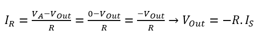
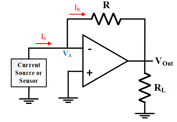
Figure 4: Op-amp circuit by considering a load resistance.
Equation 2 presents that the output voltage depends on input current, and the load presence cannot affect the output voltage, which is a perfect feature of this converter. Basically, this type of circuit is known as transimpedance amplifier because it acts like an impedance that converts current to the voltage. Moreover, the current can be amplified easily by the feedback component.
As mentioned before, the current source can be a sensor that produces the current in its output. One of the most common types of a current source is a photodiode. In fact, a photodiode takes photons in and gives the current flow out. The photodiode has an internal capacitor, which is parallel to the diode. If a simple resistor based is used, a time constant would be available that is equal to the product of resistor and photodiode capacitor, which is undesirable. The circuit is shown in Figure 5. The larger the bias voltage across the photodiode, the smaller the device’s capacitance becomes. While this is good for speed, it is limited in practice by the capability of a photodiode to withstand large reverse voltages.
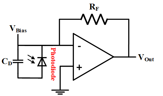
Figure 5: Photodiode circuit with transimpedance amplifier
In this configuration, there is a major problem due to parallel capacitance, which is unwanted high-frequency oscillation. The capacitor is connected to the inverting terminal and the feedback resistor. Thus, the capacitor interacts with the feedback resistor, which can form a type of low-pass filter and produce unwanted oscillation in the inverting node. To solve this problem, a parallel capacitor can be added to the feedback resistor to prevent the mentioned oscillation, as illustrated in Figure 6. In high-frequency conditions, the parallel capacitor provides a short circuit around the feedback resistance on the grounds that the capacitor impedance has an inverse relationship with frequency, and in high-frequency values, its impedance would be significantly low. Therefore, no high frequency component is available in the output.
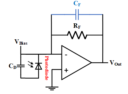
Figure 6: Photodiode configuration for preventing unwanted high frequency oscillation
Apart from the presented problem, in a practical situation, the op-amp draws a small current to bias the op-amp at inverting terminal because the op-amp is not ideal. This bias current results in an error voltage at the output and limits the dynamic range. The situation worsens by increasing the feedback resistance because the feedback resistance defines the amplification ratio, and when the current signal is amplified considerably, a small error gets significant (accuracy reduction). Therefore, a low bias op-amp selection is important for practical applications. As the ratio of the maximum output signal to noise is dynamic range, choosing a low-noise op-amp is important for transimpedance amplifier. It means that the input capacitance (combination of photodiode capacitor, internal op-amp capacitor, and board capacitor) must be in an acceptable range because a high capacitance value leads to voltage noise.
Another consideration is selecting op-amps with a FET input stage. The reason is that the input current varies in different temperatures. Op-amps with bipolar input stages have fairly constant input current. However, their currents are in the range of nano- or micro- amperes even at room temperature. Hence, unbuffered bipolar amplifiers are not appropriate for many high transimpedance gain applications. The op-amp with a FET input stage has a lower input current in the range of pico-amperes which makes it suitable for transimpedance amplifier applications. Since there are many considerations for selecting the right op-amp for transimpedance amplifier purposes, this selection would be very challenging, and, in some cases, a designer must trade-off between the characteristics to find an appropriate op-amp.
All in all, the transimpedance amplifier can be built by using simple components, including an op-amp, resistor, and capacitor. This circuit is robust against the loading effect and has a high input impedance which acts as an amplifier for optical sensors such as photodiodes to convert the sensor’s current to the measurable voltage and amplify it by adjusting the feedback resistor.
The transimpedance amplifier circuit is used in many devices that use a photodiode and need to convert current to the voltage. The typical applications are LiDAR, time of flight, surveying equipment, speed measurement devices, optical time-domain reflectometry, spectroscopy, robotics, speed measurement devices, drones, and optical communication systems like a fiber optic. All these applications include a current output of a photodiode or other sensors that would need to be processed to a voltage signal by a transimpedance amplifier.


