
Understanding RC Phase Shift Oscillator
12/07/2022, hardwarebee
Introduction to Electronic Oscillators
An electronic oscillator is a circuit that accepts DC voltage and generates a periodic AC signal with different frequencies from few Hz to GHz. The periodic signal can be sinusoidal or non-sinusoidal, like a triangle or square wave. The oscillator with a sine wave is known as a harmonic oscillator, and the oscillator with non-sinusoidal output is known as a relaxation oscillator. A wide range of applications can be introduced for electronic oscillators. For instance, they can be used for generating clock signals in SoCs/processors or generating the local carrier in radio and mobile receivers. A well-known application of electronic oscillators is in the signal generators, widely used in laboratories all around the world. This equipment generates signals with various frequencies.
In fact, an oscillator is an amplifier with positive feedback. Figure 1 shows a simple oscillator circuit consisting of two main parts: an amplifier and a feedback network. The amplifier increases the input voltage with an amplifier voltage gain of A. It means that the output voltage can be calculated as:
(1)
![]()
This voltage is given as an input to the feedback network. The feedback circuit is usually a resonant circuit with the output voltage of Vf. The feedback output voltage can be obtained by using the following equation.
(2)
![]()
where is feedback fraction. It expresses what fraction of the output voltage is delivered to the input. Using Equation 1 and 2, the output voltage of feedback network can be written as:
(3)
![]()
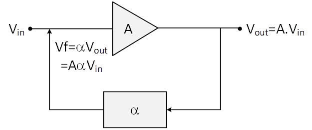
Figure 1: Simple Electronic Oscillator
Suppose the phase shift of this circuit is zero, the feedback signal is in phase with the input signal. At this time, if the feedback signal is added to the input signal and the input signal is removed simultaneously, the feedback signal will act as the input signal for this amplifier. In this case, oscillation stability depends on the amplifier and feedback gains. As a matter of fact, the product of A and , loop gain, defines the oscillator sustainability.
Three conditions can be considered for oscillators based on the loop gain. As can be seen in Figure 2, when A is less than 1, the peak voltage in each cycle decreases to reach around zero and decaying exponential pushes can be imagined for the output voltage. In contrast, when A is more than 1, the peak voltage in each cycle increases compared to the peak voltage, as shown in Figure 3. These two conditions are unsustainable. The last condition is when A is equal to 1, which means that the feedback signal is as same as the input one. In this condition, there is a stable oscillation, as depicted in Figure 4. Generally, for a sustainable oscillation, two conditions must be satisfied:
(4)
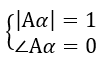
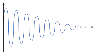
Figure 2: Output voltage when Aa is less than 1
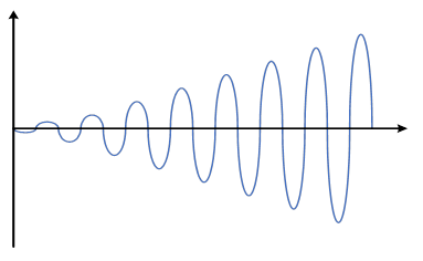
Figure 3: Output voltage when Aa is greater than 1
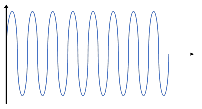
Figure 4: Output voltage when Aa is equal to 1
The mentioned conditions are known as Barkhausen’s criteria for oscillations. The interesting thing about the oscillator is that the output voltage will be received even when no input signal is available. This situation is possible due to the thermal noise in the circuit, which covers a wide range of frequencies from low to high frequencies. The frequency components of thermal noise are amplified at the first time, and then the output voltage enters the feedback circuit. As the feedback network is a resonant circuit, only a particular frequency can be passed through the feedback network, and other frequencies are filtered. Therefore, one specific frequency is added to the input noise. Initially, the loop gain of the oscillator is slightly higher than one, and the voltage is built up over the period of time. However, as the voltage reaches a certain voltage, the loop gain becomes 1 to get the sustained oscillation at the output.
The oscillators can be classified as: RC oscillators, LC oscillators, and crystal ones. In the following sections, the RC phase shift oscillator is discussed comprehensively.
RC Phase Shift Oscillator
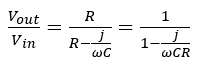
As mentioned before, the oscillator is an electronic circuit that generates periodic signals with different frequencies. In an RC phase shift oscillator, an RC circuit is placed in the feedback network to generate stable low-frequency sinusoidal signals in the range of a few Hz to some kHz like radio frequencies. In this type of oscillator, the amplifier provides a phase shift of 180 degrees. Since a phase angle of 0 or 360 degrees is required for a sustainable oscillator, the feedback circuit phase shift must also be 180 degrees. In addition to the phase angle, the product of amplifier and feedback gains should be equal to one. In the feedback network, the RC circuit configuration can be the same as the presented circuit in Figure 5. This RC circuit is a high pass filter or phase lead circuit. This naming is because the output voltage leads to the input voltage. The RC circuit transfer function is:
(5)
The phase angle of Equation 5 is:
(6)
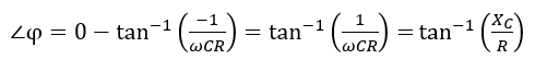
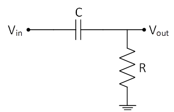
Figure 5: An RC High-Pass Filter
According to the above equation, when is equal to 0, the transfer function phase angle would be 0, and when is 0, the phase angle is 90 degrees. Therefore, the phase angle can vary from 0 to 90 degrees, but how 180 degrees phase shift can be produced? The answer is cascading two RC circuits as shown in Figure 6 because each circuit can provide a 90 degrees phase shift. To achieve 90 degrees phase shift for each circuit, the resistance should be very small (zero in theory). However, when R is very small, the circuit gain gets zero. Hence, practically, a 180-degree phase shift can not be produced by only two RC circuits. If three stages are used, each stage phase shift will be 60 degrees. The other issue, in this case, is the loading effect of other stages, but the overall phase shift would be 180 degrees. These stages can be increased, i.e., a four-stage RC phase shift circuit needs four RC circuits with 45 degrees phase shift.
The possible configurations of RC phase shift oscillator circuits with op-amps are shown in Figure 6. In these configurations, the op-amp is in the inverting mode to provide a 180-degree phase shift. In addition, the RC circuit is used to provide 180 degrees in the feedback network. It means that the overall phase shift of the oscillator is 360 degrees. In this situation, the particular frequency of the circuit can be calculated by the following equation.
(7)
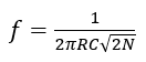
where N is the number of RC stages
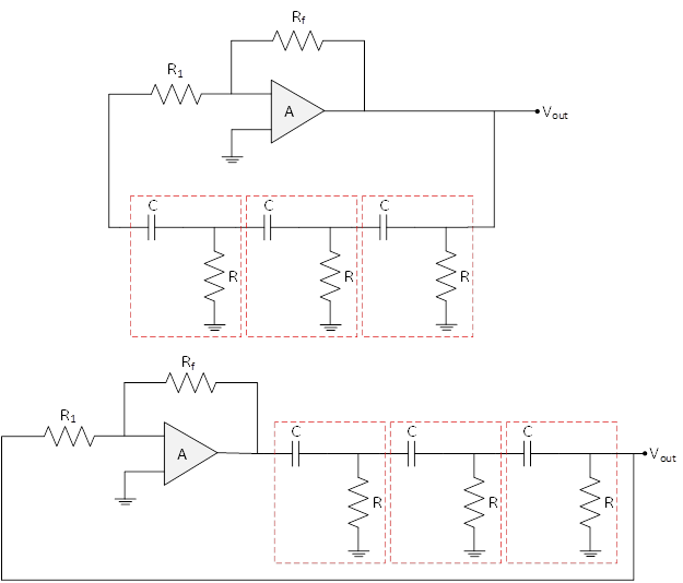
Figure 6: Possible Configurations of RC Phase Shift Oscillators
A Simple RC Phase Shift Design
Considering a three-stage RC phase shift circuit, as shown in Figure 7. To find the value of Vout/Vin nodal analysis can be applied to the circuit. In this condition, the node 2 voltage can be calculated as follows:
(8)
![]()
Then KCL can be written at this node as:
(9)
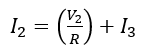
Using Equations 8 and 9, the I2 can be re-written as:
(10)
![]()
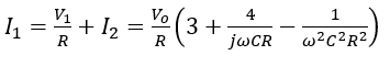
The voltage at node 1 can be obtained by using Equations 8 and 10:
(11)
![]()
Applying KCL at node 1:
(12)
All these equations are used to determine the relationship between and . Therefore, the below equation can be written.
(13)
![]()
Since the output voltage only have a real part, the imaginary parts are zero. Thus:
(14)
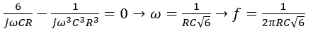
Putting Equation 13 to Equation 14, the following expression can be obtained.
(15)
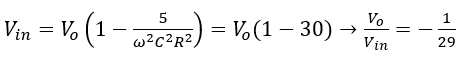
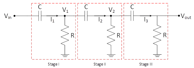
Figure 7: Three-Stage RC Phase Shift Circuit
RC Phase Shift Oscillator Advantages
The RC phase shift oscillators are simple circuits with resistors, capacitors, and op-amp or transistor. Hence, the manufacturing cost of this oscillator is low. Moreover, it has acceptable performance and stability in low frequencies like radio frequencies. The oscillator output is approximately distortion-free sinusoidal, and the oscillator does not need any negative feedback.
RC Phase Shift Oscillator Disadvantages
The RC phase shift oscillator has some disadvantages. The first drawback that can be mentioned is that the oscillator requires a strong power supply for large feedback. The frequency stability of this circuit is insignificant due to temperature changes in the circuit. Furthermore, owing to the small output voltage, it is quite challenging to create oscillation. Another disadvantage of this device is the frequency range. It cannot be used for high-frequency applications because a low capacitance is required for high frequency, and in this case, the capacitor acts like a short circuit condition.
RC Phase Shift Oscillator Applications
A mentioned, the RC phase shift oscillators can be used for low-frequency applications, such as devices which produce radio and audio frequencies. To be more specific, they are used for musical instruments, voice synthesis, and GPS units, or any other device that uses an oscillator but has a cost pressure.


