
The Ultimate Guide: Current Mirror
06/03/2023, hardwarebee
Current mirror CapStyle chanel west coast nude is a fundamental building block of modern analog IC design. They are prevalent in amplifier circuits as a biasing network and active loads and made up of active elements like BJT and MOSFET. We hope you will enjoy this current mirror tutorial.
A current mirror is an electronic circuit that is commonly used in analog circuits to copy or mirror the current flowing in one branch of the circuit to another. It consists of two or more branches, one of which is the input branch and the other is the output branch.
The current flowing through the input branch of the circuit is mirrored or copied to the output branch with a high degree of accuracy. The output current is often used to bias or drive other circuit components, such as transistors, op-amps, or other active devices.
Current mirrors can be implemented using different types of electronic components, such as transistors or diodes. They are used in a wide range of applications, including biasing circuits, power amplifiers, voltage regulators, and operational amplifiers, among others. They are a fundamental building block in many analog circuits and are used extensively in integrated circuits.
As the technology gets smaller over time, active loads imitate the behavior of the passive loads (like resistors) on integrated circuits. Discrete transistor circuits are biased to operate in the desired region of operation. It needs the resistance of suitable values. Sometimes larger output or input resistances are required. To fabricate larger resistance, it is required to have a larger die area and hence result in a larger chip area which is costly. In the case of low-bias current values, current mirrors are more cost-effective than resistors in terms of the die area required to generate a particular level of bias current. Therefore, a key factor in the effective design of analog circuits is the development of a high-performance current mirror. The IC manufacturers use this current mirror technique to replicate the current from one branch of the circuit to others.
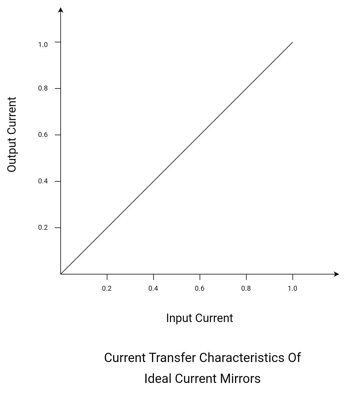
Ideally, a current mirror is defined as a current amplifier with a unity gain and high output impedance. Its output current is equal to the input current (or reference current). The idea is simple, but the generation of this ideal current mirror is rather complicated. It should have all the following characteristics.
- Replicates the reference current.
- Infinite output resistance.
- Do not vary with process variation.
- Do not vary with temperature.
- Do not vary with power supply variation.
The simplest current source consists of two matched transistors (either BJT or MOSFET). The number of transistors may vary to enhance the performance. They are extremely useful in differential amplifiers and operational amplifiers.
Basic Current Mirrors and Characteristics
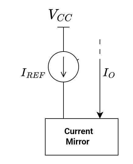
The idea behind the current can easily be explained with the help of the following block diagram.
High Output Impedance
An ideal current mirror has an infinite output resistance. Because of the high output impedance, the output current is insensitive to the impedance of the output load. In other words, it helps to keep the output current constant irrespective of the load conditions.
Practically, infinite output impedance is not possible, so it has a very high output impedance.
Low Input Impedance
An ideal current mirror typically has zero input resistance. Because of the low input impedance, the input current is insensitive to the output impedance of the input source. In other words, it helps to keep the input current constant irrespective of the drive conditions.
Whereas practically, zero input resistance is not possible, so it has a very low input impedance.
Good Frequency Response
It means they can handle input signals with minimal distortion. Ideally, it has no frequency limitations. Practically, it has limitations due to the parasitic capacitances of the transistors.
High Accuracy
A current mirror can replicate the input current with high accuracy, typically within a few percent.
Linear Current Transfer Ratio (Current Gain or Mirror Gain)
Current gain is the ratio of the output current to the input current. Ideally, it is equal to 1. For current mirrors with gain more than unity, the output current is linearly proportional to the input current. Practically, the gain is slightly less than 1.
BJT Current Mirrors
The voltage divider method is frequently used to bias BJT transistors. Look at the schematic diagram below.
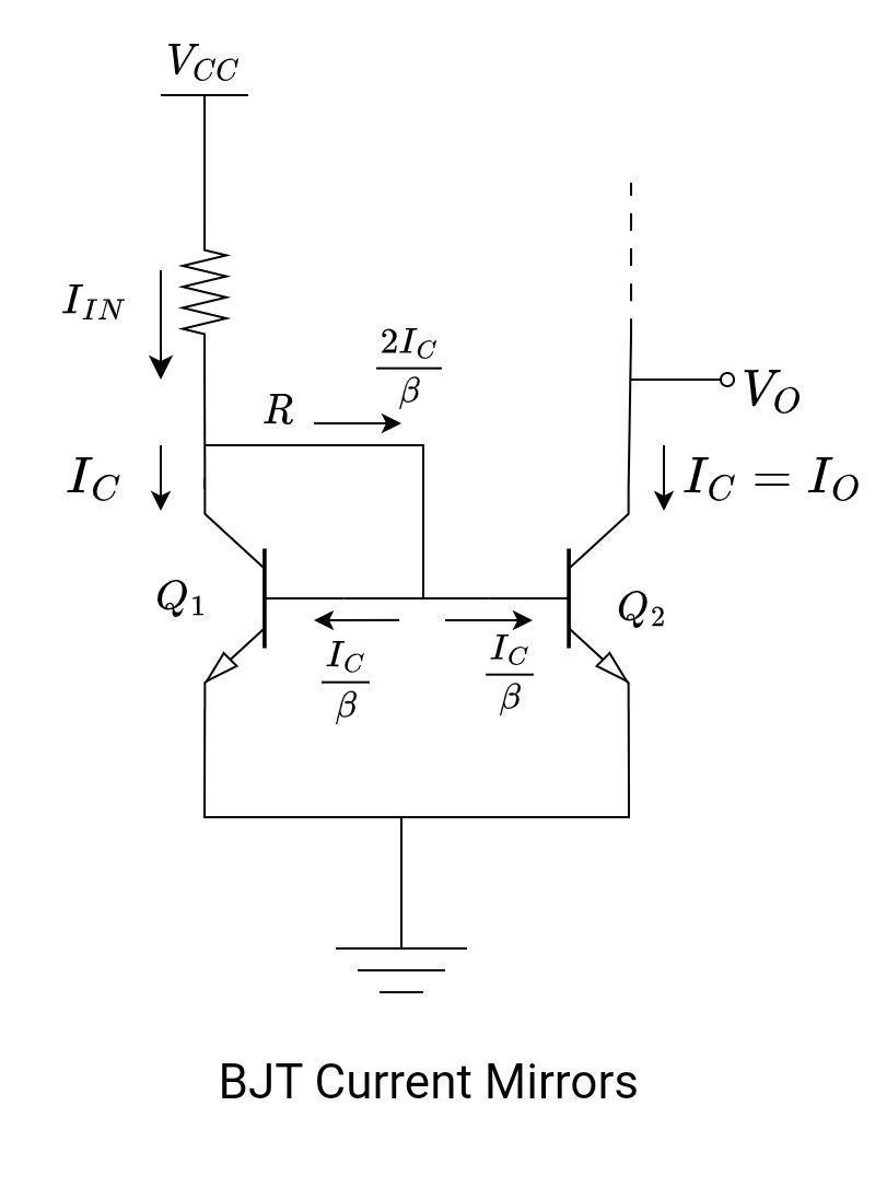
There are two transistors (Q1 and Q2) with exactly similar characteristics. Their relative areas of base-emitter junctions (EBJ) are the same. Apart from matched transistors, consider the following points as well:
- Both transistors are at the same temperature.
- They have the same DC gains.
- Both of them are in the active region.
- They must have the same base-to-emitter voltage drop values.
Practically, these conditions are possible only when both transistors are fabricated on the same chip and at the same time with the same base-to-emitter junction (EBJ) area. That’s why this method is popular in IC design.
In current mirror circuits, transistors are biased with a diode transistor. Consider the transistor Q1. The collector terminal is shorted to its base terminal. This transistor, Q1, is said to be a diode-connected transistor. Since we require matching transistors, we cannot substitute a diode for a transistor. This Q1 transistor will work in forward active mode. Look at the circuit, bases, and emitters of Q1 and Q2, which are also tied together. It means,
VBE1 = VBE2
The input current IIN flows through the diode-connected transistor Q1. The value of IIN, or the reference current, is set by VCC and R. This current establishes a voltage across Q1.
The output current, Iout or IC2 is controlled by VBE2.
Where
VT = thermal voltage
![]()
IS1 and IS2 are the transistor saturation currents; for identical transistors, they are the same.
From the above-derived equation, it is clear that the current flowing in the collector of Q1 is the same as the current flowing in the collector of Q2.
Now, find out the value of IC2 = IOUT
Apply KVL at the collector terminal of Q1.
- From the above-derived equation, it is observed that the input current is equal to the output current in the case of β >>1.
- The resistance value is responsible for regulating the value of current through the load. Be mindful when selecting the resistance value.
- Transistors in a current mirror circuit must be at the same temperature because beta varies with temperature which may result in malfunctioning.
- Current mirror circuits are strongly dependent on the matching transistors. For better accuracy, the transistors often need to be on the same substrate.
MOSFET Current Mirrors
BJT’s current mirrors are discussed in detail. Here is the MOSFET version of the current mirror. The MOSFET current mirror circuit and its working is analogous to BJT current mirror circuits
Have a look at the circuit below.
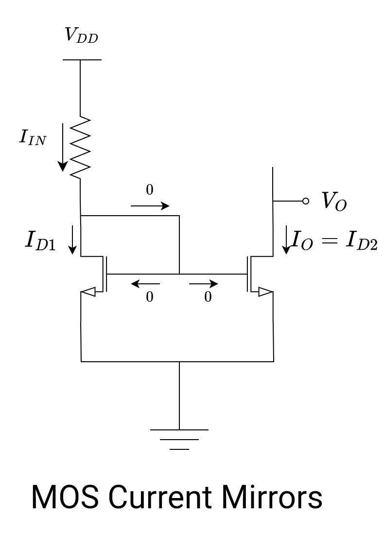
The transistor M1 is diode-connected, as discussed in the BJT case. The gate and drain terminals of M1 are connected, and hence, VGD = 0. Transistor M1 remains in saturation mode if the gate threshold voltage is positive. Also, the source terminals of both M1 and M2 transistors are connected. Assume the following:
- M2 also operates in saturation regions. This is necessary because M2 has to work as a constant current source.
- Both transistors have an infinite output resistance
- The gate-to-source voltage of both transistors is equal, VGS1 = VGS2.
- The current ID2 or IOUT is controlled by VGS2.
- Neglect channel-length modulation.
The value of current ID1 is given by the following equations:
Have a look at the circuit: VDD provides the drain current through the resistor R, and the gate current is zero.

With the help of these two equations for ID1, we can evaluate the required value of R.
Consider Q2, the drain current for saturation mode (neglect channel-length modulation) is given by,
Compare equations for ID1 and ID2,
This is the equation for the current gain or current transfer ratio.
From the above equation, it is concluded that the relationship between the input and output current of a current mirror depends on the geometry of the transistors.
For the current gain to be equal to unity, the two transistors should be identical. It means both transistors have the same W/L ratio.
![]()
Important Terms
Current Sources Versus Current Mirrors
A current source can either be a current mirror or any other source of current. The main objective of the current source is to maintain a steady current flow through a component or a circuit branch regardless of the voltage applied across it. A single transistor is all that is needed to create the most basic current source. It is not a current mirror since a current mirror replicates the same current to a different area of the circuit.

In the above figure, a single NMOS transistor is in saturation mode. It works as a current source.
Multiple Copies Of Iref
Sometimes there is a single source of current (essentially a reference current mirror). It is used to reproduce the same current in many different locations. So, the same IREF is distributed to many other subsidiary circuits.
IREF = I1 = I2 = I3
Current Mirrors Gain Other than Unity
Until now, current mirrors with unity gains have been discussed. There are possibilities to get the gain other than unity
![]()
In BJT, the base-emitter junction area determines the current scaling factor.
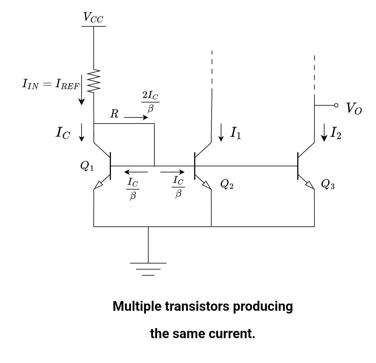
From the above equation, it is obvious that generating multiple copies of the reference current is all dependent on the area of both transistors. If another transistor is added in parallel with Q2, we get two copies of the reference current.
Let’s suppose Q1, Q2, and Q3 are identical transistors with high current gain β. Neglect the base current then,
IREF = I1 = I2
If a single transistor with a base-emitter junction area equal to that of Q2 and Q3 is used in place of the two parallel Q2 and Q3 transistors, it would generate an output current twice as large as IREF.
Current Scaling
Look at the figure below; the collectors on the output sides are connected. It will increase the magnitude of the current. As the number of transistors in parallel increases, the current increases. By connecting transistors in parallel, it will increase the EBJ area, and hence they can be replaced with a single transistor if they have the same EBJ area. In IC manufacturing, it is easy to get matched transistors, but it is difficult to achieve the same results with discrete components.
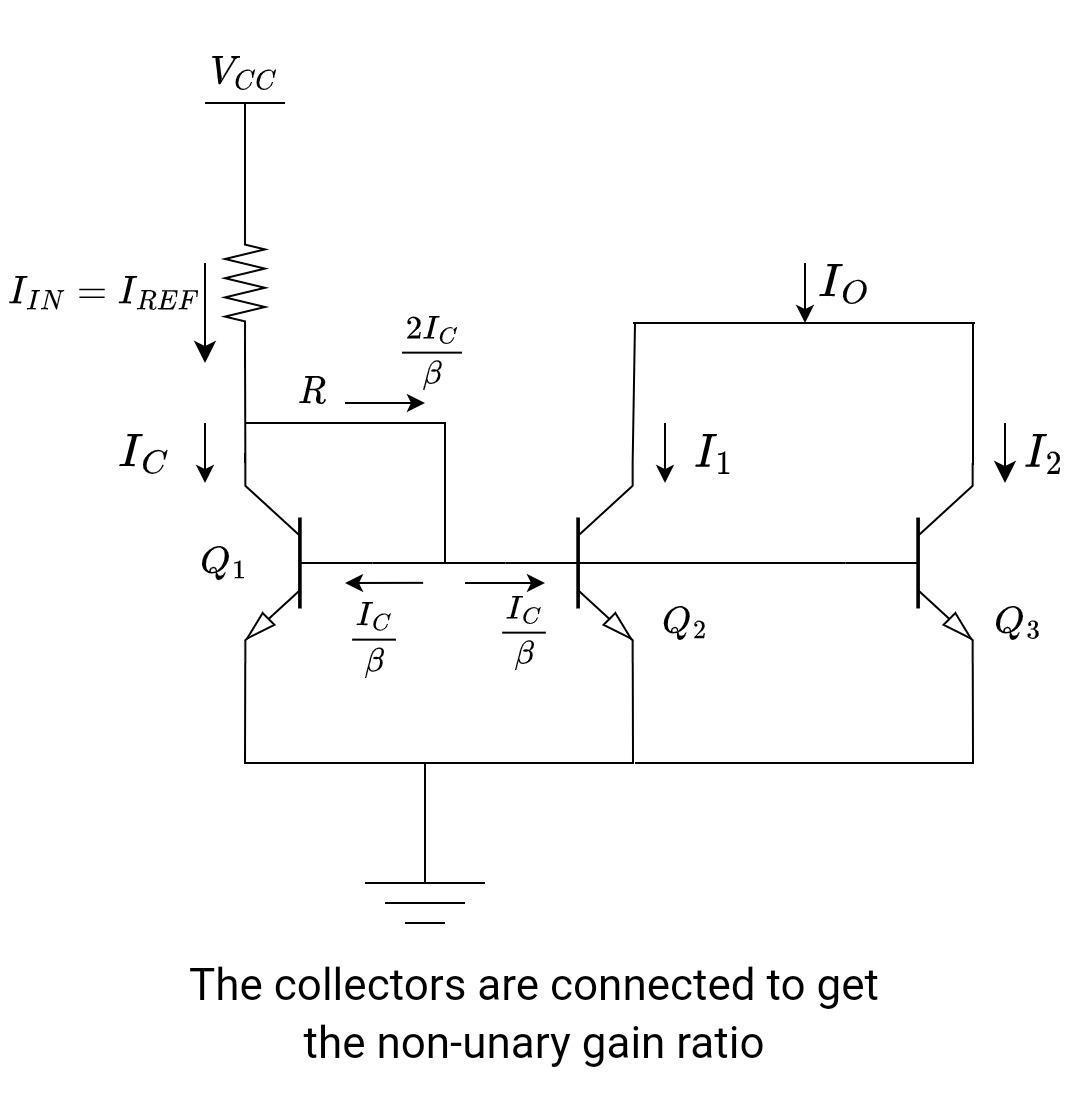
If there is a single transistor at the output side, the output current is given as:
IREF = I1
If there are transistors on the output side, the output current is given as:
IREF = 2*IO
Similarly, if there are x transistors on the output side, the output current is given as:
IO = x*IREF
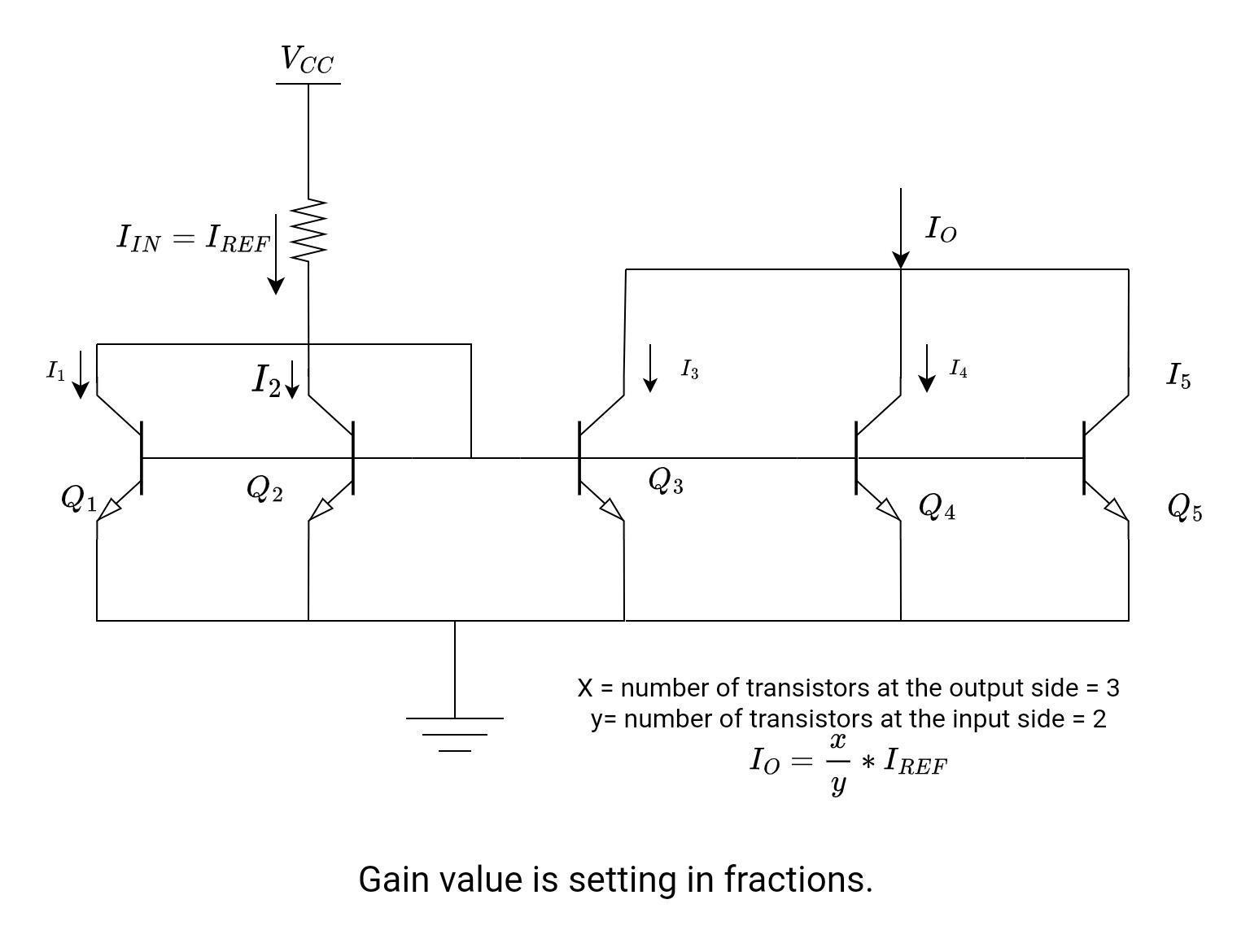
Fractional Scaling
It is possible to set the gain value in fractions as well.
- Add a transistor in parallel with a reference transistor (or the two transistors in parallel at the input side). Let’s suppose y is the number of transistors in parallel at the input side.
- Add one or more transistors in parallel at the output side. Let’s say x is the number of transistors on the output side. All of them are in parallel.
It will set the gain accordingly. Following is the relationship between input current and output current.
Current Mirror Applications
Current mirrors are used in a variety of electronic applications. Here are some common applications:
- Biasing circuits: Current mirrors are often used to establish a stable bias current for active devices such as transistors or operational amplifiers. This allows for more reliable and consistent operation of the circuit.
- Amplifier circuits: Current mirrors can be used to provide a constant current source to an amplifier circuit, allowing for more predictable and stable operation.
- Voltage regulators: Current mirrors can be used in voltage regulator circuits to provide a constant current to a load, regardless of changes in the input voltage or load resistance.
- Digital-to-analog converters: Current mirrors can be used in digital-to-analog converter circuits to provide a precise current source that is proportional to the digital input code.
- Voltage references: Current mirrors can be used in voltage reference circuits to provide a stable reference current that can be used to generate a precise voltage reference.
- Switching circuits: Current mirrors can be used in switching circuits to control the on/off times of transistors, allowing for more efficient operation.
Overall, current mirrors are a fundamental building block in many analog circuits and are used extensively in integrated circuits.


