
Summing Amplifier
03/09/2021, hardwarebee
Summing amplifier is an important circuit topology that enables us to sum signals coming from different channels in an easy and practical manner.
There are two types of summing amplifiers: inverting and non-inverting summing amplifier. As their names suggest, inverting summing amplifiers both sum and invert the input signals whereas non-inverting summing amplifiers only sum the input signals. In addition, inverting summing amplifiers are actually the extended implementation of inverting amplifiers. Similarly, non-inverting summing amplifiers are the extended implementation of non-inverting amplifiers.
It should be noted that we assumed op-amps are ideal throughout this article. When we assume that the op-amp is ideal, this means we have an infinite open-loop gain, A. The general op-amp gain equation Vout = A.( V+ – V–) implies that as A goes to infinity, V+ = V– because:
![]()
Inverting Summing Amplifier
Inverting summing amplifiers compute the inverted summation of input signals, that is, with a negative gain. This circuitry is actually not different than inverting amplifier, except multiple branches connected to the inverting input. Note that the input signals are connected to the inverting input (denoted by “–“ sign) of the op-amp.
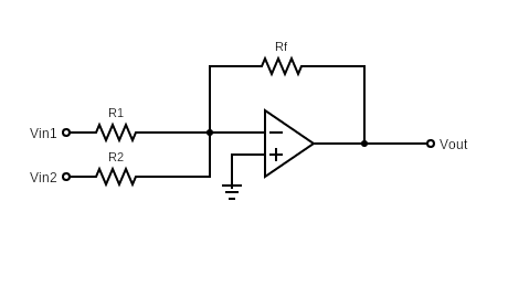
Figure 1: Inverting Summing Amplifier Schematic
As in the inverting amplifier case, the output signal is out of phase with the input signals. For instance, if your input signals are sinusoids such as Vin1 = Vin2 = sin(wt), then the output signal will be in the form of -sin(wt) = sin (wt +2π). Thus, the input and output signals are out of phase with a phase difference of 2π.
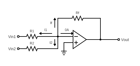
Figure 2: Inverting Summing Amplifier with current directions
For the rest of our calculations, we will assume the op-amp is ideal, i.e., we get V+ = V– = 0V as explained above. Also, note that no current flows into the op-amp’s inputs because op-amps have infinite input resistance. So, no current can flow into or out of the input ports.
In order to find the output voltage, Vout, we need to apply Kirchhoff’s Current Law.
KCL at V– node when the op-amp has infinite open-loop gain:
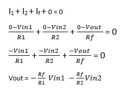
If we consider more input branches, such as Vin3 with R3, Vin4 with R4 and so on, we can simply include all the currents passing through these new resistances to the KCL equation above. This would yield the generalized equation for inverting summing amplifiers:
Generalized Equation:
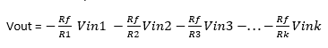
for k input branches.
The equation above demonstrates that we can add multiple signals with a negative gain (phase shift of 2π) with this simple design. The coefficients (the multiple of each input signal) are weight of each particular input signal. By changing the resistance that each input signal is connected to, you can change that input’s weight.
As it can be observed from Vout equation above, the output signal is the weighted sum of the input signals whose weight is determined by the resistance they are connected to (and Rf). In addition, the output signal is out of phase with the input signals. For instance, if Vin1 = 3sin(wt) and Vin2 = 4sin(wt) with R1=R2=Rf, you get Vout = -3sin(wt)-4sin(wt) = 7sin(wt+2π).
When you want to compute the weighted sum of the signals without a phase shift of 2π rads, you can simply connect an inverter op-amp at the Vout of the circuit.
One important application of inverting amplifier topology is Digital to Analog Converter (DAC). If digital inputs of 1’s and 0’s are connected to the input terminals Vin1, Vin2 and so on, then the output signal would be an analog signal which was obtained by the weighted sum of each digital input.
Non Inverting Summing Amplifier
Non inverting summing amplifiers sum the input signals with a positive gain. This topology is similar to non-inverting amplifier topology, but with multiple inputs this time. Note that the input signals are connected to the non-inverting input (denoted by “+” sign) of the op-amp.
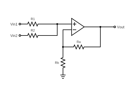
Figure 3: Non-Inverting Summing Amplifier Schematic
As explained previously, V+ = V– for ideal op-amps. However, we do not know either of the voltages in this case. Therefore, we assume V+ = V– = Vx, and try to find what Vx is by applying Kirchhoff’s Current Law at V+ and V– nodes. Also, note that no current flows into the op-amp’s inputs because op-amps have infinite input resistance. So, no current can flow into or out of the input ports.
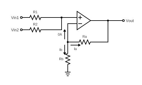
Figure 4: Non-Inverting Summing Amplifier with current directions
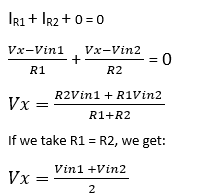
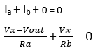
KCL at node V+ :
It should be noted that if you want to add more branches to the input, such as Vin3 with the same resistance, the Vx equation is updated as follows:
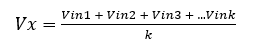
where k is the number of input branches and all inputs have the same resistance (R1 = R2 = R3 = … =Rk).
Note that we cannot generalize Vx equation as above for multiple inputs without assuming all resistances are equal.
KCL at node V– :
Note that KCL equation at node V– does not change when the number of inputs change.
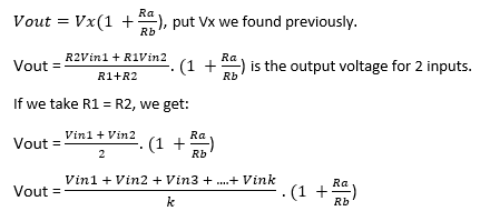
is the output voltage for k inputs when R1 = R2 = R3 = … = Rk.


