Understanding AC to DC Converter
16/12/2022, hardwarebee
Introduction
As can be implied from its name, an AC to DC converter, converts AC signals into DC ones. Generally, AC signals are periodic signals, such as sinusoidal, repeating in each cycle. In an AC system, parameters change from positive to negative and vice versa. However, in the DC system, the parameters are approximately constant, and there is no change in their values in various instances. DC parameters are required for their industrial processes in many industries, especially cement companies, copper companies, etc. Apart from that, this kind of converter is used in motor drivers and many electronic devices. In the next sections, different types of AC to DC converters using diodes and thyristors are discussed. Moreover, The AC to DC converter applications will be introduced in the last section of this article.
Basically, AC to DC converter is called a rectifier. Thus, in the some place of this article, the rectifier is used instead of the mentioned converter.
AC to DC Converter Theory
To convert AC parameters to DC ones, various types of semiconductor switches can be used in different configurations. Generally, the AC to DC converters can be categorized as half-wave and full-wave AC to DC converters. The simplest one AC to DC converter is the half-wave diode-based AC to DC converter. Other types of semiconductors are thyristors, IGBT, MOSFETs, etc.
The diode is an uncontrolled semiconductor element that allows the current to flow in only one direction and prevents the current in the reverse direction. The diode is presented schematically in Figure 1. It can also be thought of as a one-way valve. It will allow current easily in one desired direction while blocking current from flowing in the opposite direction.
Silicon makes up the majority of semiconductors, and more precise applications also employ germanium. This semiconductor device has two terminals: a cathode (negative) and an anode (positive). The diode is in forward bias and functions as a close switch when the anode voltage is higher than the cathode voltage. When the anode voltage is lower than the cathode one, the diode is in the inverse state (open switch). Therefore, the voltage level at the diode terminals is the only external control over diode operation. It is important to remember that the component’s voltage bias determines how much current can flow through a diode. In actuality, germanium diodes require a voltage of 0.3V to be triggered, while silicon diodes require a voltage of more than 0.7V. It indicates that for a diode to turn on, there must be a voltage differential between the anode and cathode higher than 0.7V; otherwise, the diode is off. The voltage drop should be considered for specific tasks, such as loss computations, even though this threshold is relatively low compared to the input voltage.
As a result, the switch closes, and the input voltage is applied to the load when the voltage in the positive half cycle rises over 0.7V. Additionally, the diode turns off when the input voltage falls below 0.7V, leaving the load voltage at zero. Because the cathode voltage is lower than the anode voltage in the negative half cycle, it is analogous to the ideal diode circuit in which the load voltage is zero.

Figure 1: Diode terminals
Single-Phase AC to DC Converter Configurations
The single-phase half-wave AC to DC converter is the simplest and easiest AC to DC converter — one that only requires one semiconductor device. This article introduces a half-wave AC to DC converter based on diodes.
An AC voltage source, a diode, and a load make up a fundamental single-phase half-wave AC to DC converter, as shown in Figure 2. The diode accepts just half of the sinusoidal voltage in the left circuit and rejects the other half. It indicates that the diode is in forward mode during the positive half cycle and reverse mode during the negative half cycle. In contrast, the diode in the right circuit accepts the negative half cycle while rejecting the positive. Two single-phase half-wave AC to DC converter setups are created in this manner.

Figure 2: Single phase half wave AC to DC converter configurations
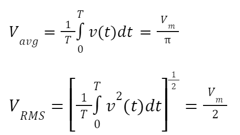
This AC to DC converter is not efficient enough because the average and RMS values in this converter are low compared to the other configurations. The half-wave AC to DC converter efficiency is 40.6 percent. Thus, it is mostly used when the rectification level is less important. For better power quality, a suitable capacitor can be installed in parallel with the load as a filter to enhance the rectification level. The average and RMS values in this AC to DC converter are defined as follows:
Another common AC to DC converter configuration is a full-wave AC to DC converter, which has better power quality and efficiency than the half-wave one. However, a full-wave AC to DC converter needs more semiconductor elements. To build a full-wave AC to DC converter, two configurations are available: a center-taped transformer configuration and a bridge configuration. These two configurations are shown in Figure 3. As can be seen, the number of diodes for the center-tapped transformer configuration is two, and this value for the bridge configuration is four. Thus, the AC to DC converter size is bigger than the half-wave AC to DC converter. Furthermore, a transformer with a tap is required for the center-tapped transformer configuration.
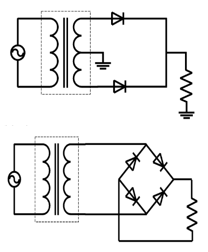
Figure 3: Center-tapped transformer configuration and bridge AC to DC converter configuration
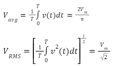
The efficiency of a full-wave AC to DC converter is 81.2%, much higher than that of a half-wave. However, the diode peak inverse voltage (PIV) for the center-tapped transformer configuration is twice the other configurations because twofold, the peak input voltage will be across the diode when it is off. This value for half-wave and bridge configurations only equals the peak input voltage. Hence, a more powerful diode should be selected for center-tapped transformer configuration to tolerate the inverse voltage. The average and RMS values for full-wave AC to DC converters can be expressed as follows:
Although a center-tapped AC to DC converter performs similarly to a bridge AC to DC converter, it requires a large space for a transformer and diodes.
Multi-Phase AC to DC Converter Configurations
When more power is required for the system, single-phase AC to DC converters cannot supply the load. Hence, multi-phase AC to DC converters must be employed to address the system’s needs. The higher number of phases will lead to better power quality, but more semiconductor elements and connections make the AC to DC converter more complex. The principle of a multi-phase AC to DC converter is the same as a single-phase AC to DC converter. For instance, one diode is in series with each phase of the source to create a three-phase half-wave AC to DC converter, as shown in Figure 4. In this configuration, the neutral point must be accessible for load connection. Hence, the transformer secondary in this configuration must be a star to provide a neutral point. The average and RMS values for half-wave three-phase AC to DC converters can be expressed as follows:
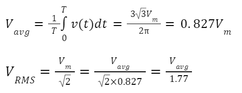
Moreover, half-wave three-phase AC to DC converter efficiency is around 97 percent, showing that multi-phase AC to DC converters have better power quality and efficiency, which are required for some special applications. This configuration can be extended to 6, 12, 18, and 24-phase AC to DC converters, which are utilized when a lower ripple is required in DC output.
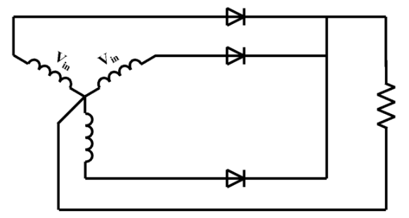
Figure 4: Three-phase half-wave AC to DC converter
Bridge configuration is more common for full-wave three-phase AC to DC converters, and center-tapped three-phase AC to DC converters are not used in industry. In a three-phase bridge AC to DC converter, both star and delta connections can be used for the transformer secondary because a neutral point is not necessary for this AC to DC converter. As an example, a three-phase bridge AC to DC converter with a delta connection in the transformer secondary is illustrated in Figure 5.
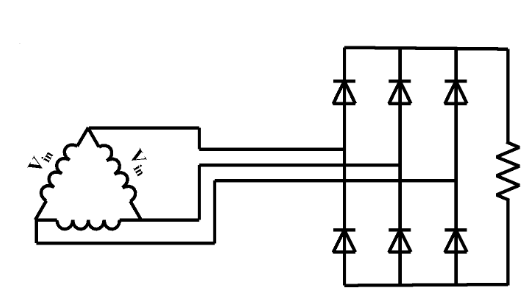
Figure 5: Three-phase full-wave bridge AC to DC converter
As can be seen, six diodes are available in this configuration. However, the ripple in this configuration is lower than in the three-phase half-wave AC to DC converter. Moreover, it has higher efficiency, equal to 99.87 percent. Other bridge configurations with 6, 12, 18, and 24 phases are also applicable.
Controlled Elements for AC to DC Converter
In previous sections, the diode was the main element in AC to DC converters. As mentioned, the diode is an uncontrolled element, and on or off conditions are based on the voltage/current values. However, other semiconductor switches can be used in AC to DC converters. For instance, the thyristor is a controlled switch that can be turned on by injecting a pulse into its gate. This switch is quite similar to a diode. Other switches, such as IGBT and MOSFET, can be used if more control is required.
Steps in Designing an AC to DC Converter
- Determine the desired output DC voltage and current. This will help you determine the size and type of converter you need to build.
- Select a AC to DC converter circuit. There are several types of AC to DC converter circuits that can be used to convert AC to DC, including full-wave AC to DC converters, half-wave AC to DC converters, and bridge AC to DC converters. Choose the one that best meets your needs.
- Choose a filter circuit. A filter circuit is used to smooth out the ripple present in the DC output of the AC to DC converter. There are several types of filter circuits that can be used, including capacitor filters and inductor filters.
- Design the power stage. The power stage is responsible for converting the DC voltage from the AC to DC converter and filter circuit to the desired output DC voltage. This can be done using a voltage regulator, a transformer, or a combination of both.
- Test and optimize the converter. Once you have built the converter, it is important to test it and make any necessary adjustments to optimize its performance. This may involve adjusting the values of components, changing the type of AC to DC converter or filter circuit used, or adjusting the power stage.
AC to DC Converter Applications
AC to DC converter is an inevitable part of power electronics and electronics. With growing of the power electronic devices in the system, AC to DC converters are utilized in different circuits to convert AC parameters to DC ones, especially in HVDC systems. Furthermore, to reduce the air pollution caused by factories, industrial AC to DC converters are used to absorb pollutants by positive and negative surfaces, which are connected to AC to DC converter outputs. In aluminum, copper, and other metal refinery factories, AC to DC converters are the main part of the process.
AC to DC converters are also found in electronic devices that we use in our daily life. For instance, an AC to DC converter detects the signal peak in AM radio. Moreover, AC to DC converters are used in multimeters, electric welding, modulations, chargers, LED televisions, and so on, and AC to DC converters are available. It can be concluded that this important converter is the main part of our lives, and according to the system’s needs, various configurations can be selected.
- Charging electronic devices: AC to DC converters are often used to charge electronic devices, such as smartphones, laptops, and tablets, by converting the AC power from a wall outlet into the DC power required by these devices.
- Powering DC motors: AC to DC converters are used to power DC motors in a variety of applications, including electric vehicles, industrial equipment, and appliances.
- Operating LED lighting: AC to DC converters are used to power LED lighting systems in homes, businesses, and public buildings, as LEDs require a DC power source to operate.
- Running electronic circuits: AC to DC converters are used to power electronic circuits in a variety of applications, including computer systems, security systems, and telecommunication systems.
- Charging batteries: AC to DC converters are used to charge batteries in a variety of applications, including portable electronic devices, power tools, and backup power systems.
- Operating solar panels: AC to DC converters are used to power solar panels and charge batteries in off-grid solar energy systems.
- Running electrical appliances: AC to DC converters are used to power a variety of electrical appliances, including refrigerators, air conditioners, and washing machines.
- Operating electronic signs: AC to DC converters are used to power electronic signs and displays, such as LED billboards and neon signs.
- Running audio and video equipment: AC to DC converters are used to power audio and video equipment, such as televisions, stereo systems, and speakers.
- Operating medical equipment: AC to DC converters are used to power medical equipment, such as ventilators, defibrillators, and monitoring systems.


