This website uses cookies so that we can provide you with the best user experience possible. Cookie information is stored in your browser and performs functions such as recognising you when you return to our website and helping our team to understand which sections of the website you find most interesting and useful.
Understanding Impedance of Capacitor
07/08/2023, hardwarebee
A capacitor’s resistance to the flow of alternating current (AC) is referred to as its impedance. Like resistance, impedance is unique to AC circuits because it considers the amplitude and phase shift of the current relative to the voltage. Although impedance is similar to resistance, it is not the same as it. In this article we will discuss the impedance of a capacitor and the impedance of a capacitor formula.
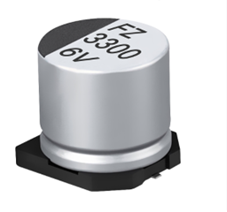
The impedance of a capacitor is frequency-dependent and can be represented as follows formula:
Zc = 1 / (jωC)
where
- Zc is the impedance of the capacitor (measured in ohms, Ω)
- j is the imaginary unit ()
- ω is the angular frequency of the AC signal (measured in radians per second)
- C is the capacitance of the capacitor (measured in farads, F)
In this equation, the capacitance (C) and angular frequency (ω) are inversely proportional to the impedance (Zc). Hence, more current can pass through the capacitor when its impedance reduces with increasing frequency. In contrast, the impedance rises at lower frequencies, limiting the flow of current.
The capacitor’s impedance approaches 0 at very high frequencies, acting practically like a short circuit. The impedance increases dramatically at very low frequencies, causing the capacitor to behave like an open circuit.
In AC circuit analysis, capacitor impedance is a key concept that is important for understanding filter circuits, power factor correction, and many other applications. When building and analyzing AC circuits, it is crucial to take capacitor impedance into account to ensure correct operation and performance.
Calculating Capacitor Impedance
You need to know the frequency (f) of the AC signal and the capacitance (C) of the capacitor to determine the impedance (Zc). Impedance has a magnitude and a phase angle since it is a complex quantity. The following formula can be used to determine a capacitor’s impedance.
To calculate the impedance, follow these steps:
- Convert the frequency (f) of the AC signal to angular frequency (ω):
ω = 2πf
Here, 2π is used to convert the frequency from hertz (Hz) to radians per second.
- Use the angular frequency and the capacitance to calculate the impedance:
Zc = 1 / (jωC)
- To express the impedance in its polar form (magnitude and phase angle), you can convert the complex number from the previous step:
Zc = |Zc|∠θ
The magnitude |Zc| is given by:
|Zc| = 1 / (ωC)
The phase angle θ is given by:
θ = -π/2 (or -90 degrees)
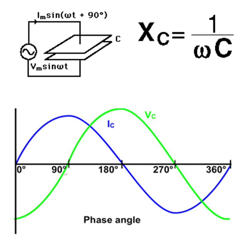
The negative sign in the phase angle is because the current leads the voltage in a capacitor by 90 degrees.
Let’s go through an example calculation:
Example: Calculate the impedance of a capacitor with a capacitance of 100 μF at a frequency of 50 Hz.
Step 1: Convert frequency to angular frequency:
ω = 2π * 50 Hz = 314.16 rad/s
Step 2: Calculate impedance:
Zc = 1 / (j * 314.16 rad/s * 100 μF)
Step 3: Calculate the magnitude and phase angle:
|Zc| = 1 / (314.16 rad/s * 100 μF) ≈ 31.83 Ω
θ = -π/2 ≈ -1.5708 radians (or -90 degrees)
Thus, the impedance of the capacitor is approximately 31.83 Ω with a phase angle of -90 degrees.
Application of Capacitor Impedance
The concept of capacitor impedance finds various practical applications in electrical and electronic circuits. Some of the significant applications of capacitor impedance include:
- Filter Circuits: Capacitors are essential components in filter circuits, where they are used to block certain frequencies of AC signals while allowing others to pass through. The impedance of the capacitor at a particular frequency determines its filtering capability.
- Power Factor Correction: In AC power systems, certain loads can cause a phase difference between voltage and current, resulting in a low power factor. Capacitors are used for power factor correction by providing leading reactive power, which helps to improve the power factor and reduce energy losses.
- Coupling and Decoupling Capacitors: Capacitors are used in coupling and decoupling applications to allow AC signals to pass between stages of an electronic circuit while blocking any DC component. Impedance plays a crucial role in determining the frequency response and filtering properties in these applications.
- Tuned Circuits: Capacitors are used in conjunction with inductors to create resonant or tuned circuits. The impedance of the capacitor affects the resonance frequency and the bandwidth of such circuits.
- Energy Storage: Capacitors are energy storage devices, and their impedance affects how quickly they can charge and discharge in different applications.
- Signal Coupling and AC Coupling: In audio and communication circuits, capacitors are used for signal coupling and AC coupling to remove any DC offset while allowing the AC signals to pass through.
- Voltage Regulators and Power Supplies: Capacitors are used in voltage regulators and power supplies to smooth out voltage fluctuations and provide stable DC output. The impedance of capacitors affects their ability to store and release charge as needed.
- Transient Suppression: Capacitors are used for transient suppression in circuits to protect sensitive components from voltage spikes and surges. The impedance of capacitors at high frequencies is essential for effective transient suppression.
- Motor Run Capacitors: In electric motors, running capacitors help improve efficiency and the starting torque. The impedance of these capacitors influences their performance.
- RF Circuits: In radio frequency (RF) circuits, capacitor impedance affects signal coupling, filtering, and impedance matching.
Types of Capacitor Impedance in Electrical Circuits
In electrical circuits, the impedance of capacitors can manifest in different forms, depending on the frequency of the alternating current (AC) signal and the type of circuit they are used in. Here are the primary types of capacitor impedance encountered in electrical circuits:
- Capacitive Reactance (Xc): Capacitive reactance is a type of impedance that arises in capacitors when subjected to an AC signal. It is the opposition to the flow of alternating current and is inversely proportional to the frequency of the AC signal and the capacitance of the capacitor. The formula for capacitive reactance is:
Xc = 1 / (2πfC)
where
- Xc is the capacitive reactance (in ohms, Ω)
- π is the mathematical constant pi (approximately 3.14159)
- f is the frequency of the AC signal (in hertz, Hz)
- C is the capacitance of the capacitor (in farads, F)
Capacitive reactance decreases as the frequency increases while increases as the frequency decreases.
- Impedance Magnitude: The magnitude of capacitor impedance represents the overall opposition to the flow of AC current offered by the capacitor. It is the absolute value of capacitive reactance and is calculated using the same formula as capacitive reactance:
|Zc| = |Xc| = 1 / (2πfC)
Impedance magnitude is a measure of how strongly the capacitor resists the flow of AC current at a specific frequency.
- Phase Angle: The phase angle of capacitor impedance represents the phase shift between the voltage and current in a capacitor. Capacitors introduce a 90-degree phase shift in the current relative to the voltage. The phase angle is negative (-90 degrees or -π/2 radians) to indicate that the current lags the voltage in a capacitor circuit.
- Frequency-Dependent Behavior: Capacitor impedance is frequency-dependent. As the frequency of the AC signal changes, the impedance of the capacitor also changes. At low frequencies, the impedance is high, acting as an open circuit. At high frequencies, the impedance is low, behaving like a short circuit.
These different aspects of capacitor impedance are crucial in various electrical and electronic applications, as they determine how capacitors interact with AC signals and influence the performance of circuits in filtering, coupling, energy storage, power factor correction, and many other applications. Engineers and designers consider capacitor impedance to optimize circuit performance and achieve specific design goals.
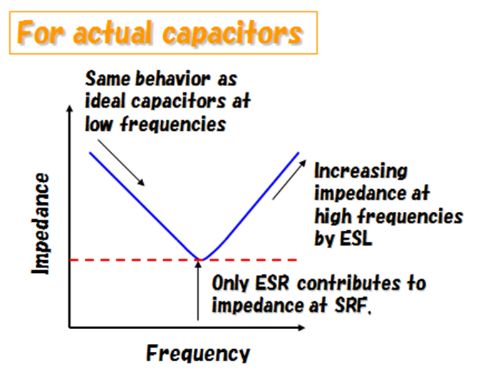
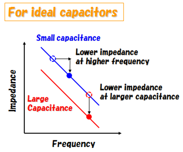
Capacitor Impedance Frequency Response
The frequency response of a capacitor’s impedance refers to how the impedance of the capacitor changes with varying frequencies of the AC signal. As the frequency of the AC signal changes, the impedance of the capacitor also changes due to its capacitive reactance. The frequency response of capacitor impedance is an essential consideration in many electronic circuits, especially in AC and audio applications.
Let’s analyze the frequency response of a capacitor’s impedance:
- Low Frequency (f 1/ (2πC)): The capacitive reactance increases dramatically at very low frequencies and eventually reaches infinity. As a result, very little current may pass through the capacitor, making it behave like an open circuit. In other words, the capacitor has a very high impedance.
- Mid-frequency signals: The capacitive reactance diminishes with increasing frequency. The capacitor’s impedance goes down as a result. As the frequency rises, more current can pass through the capacitor.
- High Frequency (f >> 1/ (2πC)): The capacitive reactance becomes tiny and almost nil at very high frequencies. With little resistance to the current, the capacitor behaves like a short circuit. At high frequencies, the capacitor’s impedance is very low.
- Resonance Frequency: In certain cases, capacitors can be part of resonant circuits when combined with inductors. At the resonant frequency, the capacitive reactance and inductive reactance can cancel each other out, leading to an exceptionally low impedance or a high impedance, depending on the circuit design.
The graph of the capacitor impedance versus frequency generally shows a downward-sloping curve on a logarithmic scale. It starts from high impedance at low frequencies, decreases as the frequency increases, and eventually levels off at a low impedance value at high frequencies.
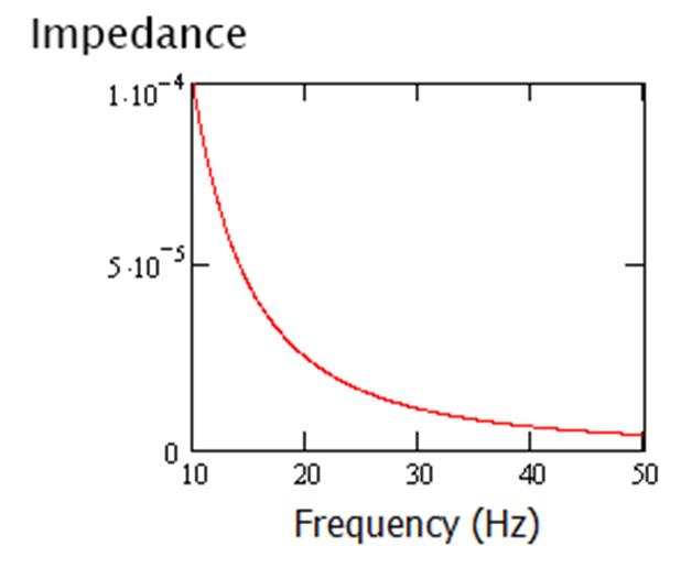
The frequency response of capacitor impedance is crucial in various applications such as filtering, coupling, and impedance matching. Engineers consider this response to design circuits that perform specific functions based on the frequency of the input signals. Additionally, it is essential to choose capacitors with appropriate capacitance values for different frequency ranges in different applications.
[1] https://www.yuden.co.jp/cs/product/support/faq/q007.html


