Power Dissipation
02/08/2022, hardwarebee
Power dissipation is a factor in electronics that plays an important role in designing various electronic circuits. When a designer wants to choose an appropriate component for an electronic circuit, power dissipation must be taken into account.
What is Power Dissipation?
When a current passes through a resistor, a part of electrical power is dissipated, which usually is converted to heat. This part of power is undesirable and cannot be used in most cases, although it is used for a few heating purposes. Hence, it is called power dissipation or “power loss”. All electronic components have internal resistors, which can be neglected in some cases. For example, in ideal form, capacitors and inductors do not have any power dissipations because they are energy storage devices, and their internal resistors can be typically neglected. The mentioned internal resistance produces heat and increases the component temperature. If the produced heat exceeds the tolerance level of the component, it will be failed and can cause problems for the designed circuit. Thus, for higher reliability of the circuit, the power dissipation of each component and the circuit as a whole must be calculated and checked by the specifications of the available components in the circuit. To calculate the power dissipation, some basic equations must be defined in the next section.
Power Dissipation Calculation
Any kind of resistor in the circuit has a power rating that expresses the amount of dissipated power that the resistor can handle. More than the defined rated power, the resistor may get burnt out. For this reason, calculating the power dissipation of a resistor is necessary for designing an electronic circuit. Before calculating the dissipated power, the well-known Ohm’s law should be explained. This law states that the current that flows through resistor is proportional to the voltage across the resistor. Ohm’s law can be written as:
(1)
![]()
where R is the resistance, V is the voltage across the resistor or voltage drop, and I is the current flowing through the resistor, as shown in Figure 1.
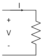
Figure 1: Current and Voltage of a Resistor
The electric power can also be calculated by the following equation which is the product of current and voltage of a resistor.
(2)
![]()
where P is the electric power. Now, the dissipated power in the resistor must be determined. Using Equation 1 and 2, the power that dissipated in the component is obtained as:
(3)

Let’s see a simple example of dissipated power calculation in the next section.
A Sample Circuit for Calculation of Power Dissipation
Considering a 100-ohms resistor is supplied by a battery, as shown in Figure 2. In ideal condition, there is no internal resistance in the DC source. As the resistor is directly connected to the DC source, the voltage across the resistor is equal to the DC source voltage. The current flowing through the resistor can also be calculated by Equation 1, as follows:
(4)

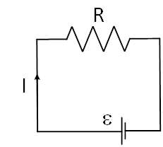
Figure 2: A resistor connected to a battery without internal resistor
With these parameters, the dissipated power is determined as:
(5)

As can be seen, r the dissipated power of the sample circuit is 1W with different equations. However, in real world, the DC source has an internal resistor of r, as shown in Figure 3. If r=1 ohm, the parameters would be as:
(6)

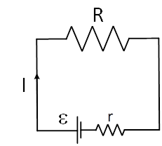
Figure 3: A resistor connected to a battery without internal resistor
The result shows that internal resistor can be neglected because it does not have a considerable impact on power dissipation. Nevertheless, what if the external resistor is small? In this condition, the internal resistance cannot be neglected and must be considered in calculations. The differentiating power to resistance must be equal to zero to determine the maximum dissipated power in the presented circuit. The dissipated power is:
(7)

The differentiating of Equation 9 is:
(8)

By solving Equation 8, the result would be:
(9)
![]()
By putting Equation 9 in Equation 7, the maximum dissipated power is:
(10)

Power Dissipation in Series and Parallel Configurations
Resistors in the circuit can be in series or parallel. A sample of series configuration is shown in Figure 4 with an ideal battery. As the resistors are series, the equivalent resistance will be the sum of the resistances. The power dissipation of components in this circuit will be:
(11) (12) (13)
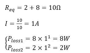
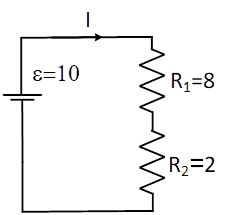
Figure 4: Series resistors in the circuit
As can be seen, the dissipated powers of R1 and R2 are 8 and 2 W, respectively. In this case, the battery power is 10W, which is the sum of the dissipated powers of the resistors. The battery power can also be calculated as:
(14)
![]()
Now, the parallel configuration is shown in Figure 5. In this condition, the voltages across resistors are equal to the battery voltage because they are in a parallel configuration. Thus, the dissipated power of each resistor can be calculated as follows:
(15)
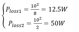
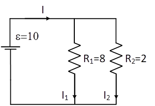
In the parallel configuration, the battery power is 62.5W which is much higher compared to the series configuration. It can be concluded that the parallel resistors have more dissipated power compared to the parallel ones (same voltage source). It is worth noting that the resistance value of a resistor can be changed by temperature. Generally, by increasing the temperature, the resistance increases based on the resistor materials, and more power is dissipated in the resistor. However, the mentioned change in the resistance can be neglected in most cases.
Handling Power Dissipation in an Electronic Circuit
Sometimes the dissipated power in the circuit is higher than the tolerance level of a component. In this condition, the component temperature may cause damage. To solve this problem, the temperature of the component must be reduced. Therefore, various cooling systems are used in electronic devices to cool down the component to control the device temperature and avoid any damage. Heat-sink is a common method for reducing the circuit temperature. In fact, a heat-sink absorbs heat from the component and transfers it to the air quickly to decrease the temperature of the component. Another method is adding a fan to cool down the temperature. All in all, by cooling systems, more current and power can be absorbed from the source, and the component lifetime will be increased.
Conclusions
As described in the article, the power is dissipated in resistors as heat. This loss of power is mostly undesirable because the produced heat cannot be used for useful purposes. However, this feature can be used for heating purposes like electric heaters, which employ high-resistance wires to produce heat. Another usage of the power dissipation is in tungsten filaments light bulb which dissipated energy is converted to light. Apart from the pros and cons of power dissipation, the designers must always check the requirements of the components in terms of temperature and power dissipation to improve the circuit lifetime and reliability.


