
Radar Sensor Chips Overview and Comparison
20/04/2023, hardwarebee
In this article, we provide an overview of radar sensor chips, their uses and benefits, and how they work. Then we step further and discuss the market, the applications. At the end, we compare a few radar chips features to help you make a decision on which radar chip to use in your application.
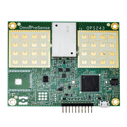
Figure 1: Doppler radar sensor
Radar Sensors Overview
Radar sensors are technological tools that use radio waves to find nearby things. The term “radar” stands for “Radio Detection and Ranging”. Radar sensors work by emitting a radio wave signal, which then bounces off objects in their path and returns to the sensor. The sensor analyzes the returned signal to determine the distance, speed, and location of the object.
Radar sensors have a wide range of applications, including:
- Automotive radar: used for advanced driver assistance systems (ADAS) such as collision avoidance, blind spot detection, and lane departure warning.
- Aviation radar: used for air traffic control, weather monitoring, and collision avoidance.
- Maritime radar: used for navigation, collision avoidance, and search and rescue operations.
- Military radar: used for surveillance, target detection, and missile guidance.
- Weather radar: used for meteorology and predicting severe weather events.
There are two main types of radar sensors: pulsed radar and continuous wave (CW) radar. Pulsed radar emits short pulses of radio waves and measures the time it takes for the pulse to bounce back to the sensor. CW radar emits a continuous stream of radio waves and measures the frequency shift caused by the object’s motion.
Radar sensors have several advantages over other types of sensors, including their ability to operate in all weather conditions and their long-range detection capabilities. However, they can also be more expensive and complex to implement than other types of sensors.
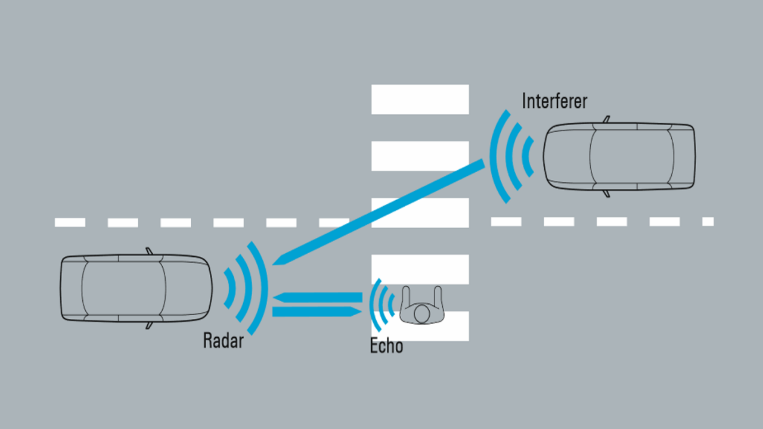
Figure 2: Radar sensor automotive application (source: R&S)
Small Radar Chips
Small radar chips are compact electronic components that contain all the necessary components for a radar system in a single package. These chips typically use CMOS (complementary metal-oxide-semiconductor) technology, which allows for the integration of analog and digital components on a single chip.
Small radar chips have a wide range of applications, including:
- Smart homes: used for motion detection, people counting, and occupancy sensing.
- Automotive: used for parking assistance, blind spot detection, and collision avoidance.
- Industrial: used for object detection, level sensing, and positioning.
- Healthcare: used for monitoring vital signs, detecting falls, and tracking movement.
One of the main advantages of radar chips is their size and low power consumption, which makes them ideal for use in battery-powered devices or in applications where space is limited. Additionally, the integration of all necessary components onto a single chip reduces the complexity and cost of designing and building a radar system.
Several companies manufacture small radar chips, including Texas Instruments, Infineon, and NXP Semiconductors. These chips typically operate at frequencies between 24 GHz and 60 GHz and have a range of up to several meters, depending on the specific chip and application.
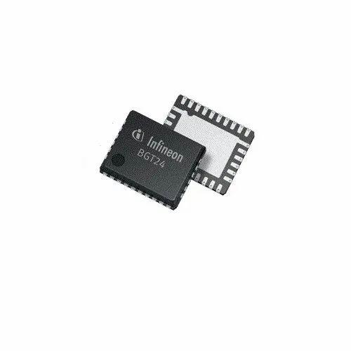
Figure 3: Infineon 24 GHz Radar Sensor
How does a Radar Sensor Work?
A radar sensor works by emitting a radio wave signal and then detecting the reflection of that signal off of an object. The time it takes for the signal to bounce back to the sensor is used to determine the distance to the object. Additionally, by analyzing the properties of the reflected signal, a radar sensor can determine other characteristics of the object, such as its speed, direction, and size.
Here are the basic steps in how a radar sensor works:
- The radar sensor emits a radio wave signal, typically in the microwave frequency range. This signal travels through the air at the speed of light.
- When the signal encounters an object, a portion of the signal is reflected back to the radar sensor.
- The radar sensor receives the reflected signal and measures the time it took for the signal to travel from the sensor to the object and back again. This time measurement is called the “time of flight”.
- Using the time of flight and the speed of light, the radar sensor can calculate the distance to the object.
- By analyzing the frequency and phase shift of the reflected signal, the radar sensor can determine other characteristics of the object, such as its speed and direction of movement.
Different types of radar sensors use different methods to emit and receive radio wave signals. For example, pulsed radar emits short bursts of radio waves, while continuous-wave radar emits a continuous signal. Additionally, some radar sensors use multiple antennas to detect signals from different angles, allowing them to determine the position and shape of an object in three dimensions.
Overall, radar sensors are useful for a wide range of applications, including automotive safety systems, air traffic control, weather monitoring, and military surveillance.

Figure 4: How does a radar sensor work
Radar Chips Features and Benefits
Radar Sensor Frequency Range
The frequency range of radar sensors can vary depending on the specific application and technology used. However, the most common frequency range for radar sensors is between 1 GHz to 100 GHz. Here are some examples of radar frequency ranges and their typical applications:
- 24 GHz: This frequency range is commonly used in automotive radar systems for applications such as adaptive cruise control, blind spot detection, and collision avoidance.
- 77 GHz: This frequency range is also used in automotive radar systems for higher-performance applications such as autonomous emergency braking, forward collision warning, and pedestrian detection.
- 122 GHz: This frequency range is used in short-range radar (SRR) systems for applications such as parking assistance, automatic door openers, and gesture recognition.
- 60 GHz: This frequency range is used in millimeter-wave radar systems for applications such as industrial sensing, traffic monitoring, and high-resolution imaging.
Higher frequency radar systems tend to have better resolution and accuracy, but they have shorter ranges and are more sensitive to interference from obstacles and weather conditions. Lower-frequency radar systems can operate over longer ranges and are less sensitive to interference, but they typically have lower resolution and accuracy.
It’s also worth noting that different countries and regions have different regulations and standards for radar frequencies and power levels. Therefore, the specific frequency range used for a given radar system may be influenced by these factors as well.
Radar Sensors Functional Range
The functional range of a radar sensor refers to the maximum distance at which it can detect and measure an object. The functional range of a radar sensor depends on several factors, including the frequency of the radar signal, the power of the transmitter, the sensitivity of the receiver, and the size and reflective properties of the target object.
The functional range of radar sensors can vary widely depending on the specific application and technology used. Here are some examples of typical functional ranges for different types of radar sensors:
- Short-range radar (SRR): SRR systems typically operate at frequencies between 24 GHz and 80 GHz and have a functional range of up to 30 meters.
- Medium-range radar (MRR): MRR systems typically operate at frequencies between 2 GHz and 18 GHz and have a functional range of up to 150 meters.
- Long-range radar (LRR): LRR systems typically operate at frequencies between 2 GHz and 10 GHz and have a functional range of up to several kilometers.
It’s important to note that the functional range of a radar sensor can be affected by a variety of factors, including weather conditions, terrain, and the presence of obstacles. For example, rain or snow can absorb or scatter radar signals, reducing the effective range of the sensor.
Additionally, the effective range of a radar sensor may be limited by the size and reflective properties of the target object. Small or low-reflectivity objects may be difficult to detect at longer ranges, while larger or highly reflective objects may be detected at greater distances.
In summary, the functional range of a radar sensor is an important factor to consider when designing and using radar systems. It’s important to choose a radar sensor with a functional range appropriate for the specific application and to take into account factors that may affect the effective range of the sensor.
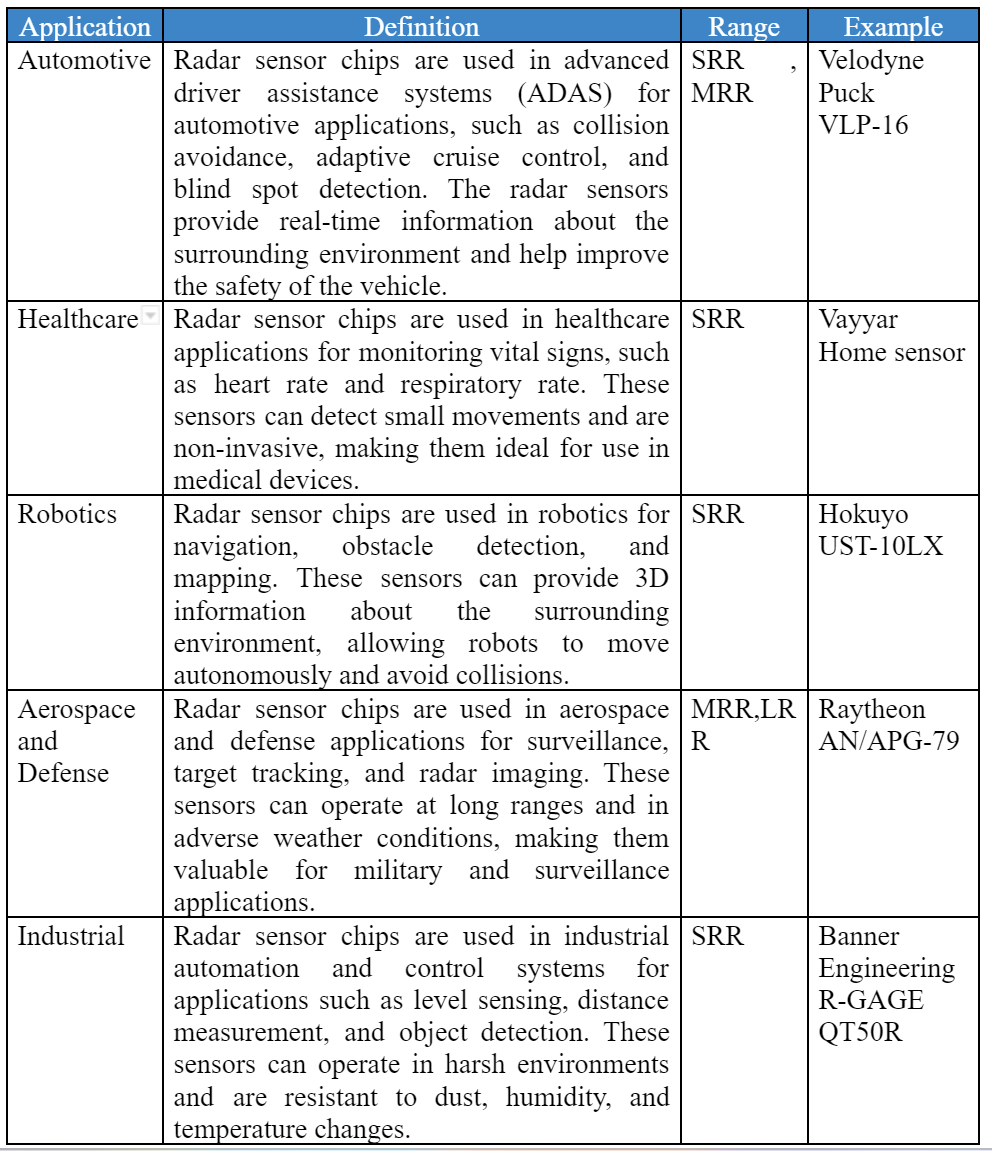
Radar Sensors Applications
Radar sensor chips have a wide range of applications across various industries. Here are a few examples:
About Vayyar Home sensor:
This sensor uses radio frequency technology to provide 3D imaging of the surrounding environment, which can be used for a variety of healthcare applications.
The Vayyar Home sensor can be used for fall detection and prevention, allowing caregivers to monitor elderly or disabled individuals who are at risk of falling. The sensor can also be used for vital sign monitoring, providing real-time data on heart rate and respiratory rate without the need for physical contact.
In addition, the Vayyar Home sensor can be used for sleep monitoring, providing information on sleep quality and, detecting sleep apnea. The sensor can also be used to monitor movement patterns, which can be useful for diagnosing conditions such as Parkinson’s disease.
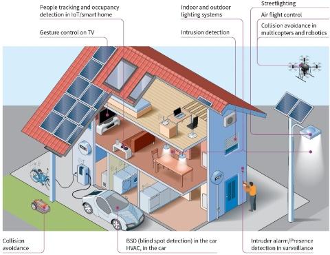
Figure 5: Using 24GHz radar sensors in Smart home (source: Infineon)
Radar Chips Definition
A small radar chip, also known as a radar system-on-chip (SoC), is a compact electronic component that integrates all the necessary components of a radar system onto a single chip. This includes components such as the transmitter, receiver, signal processor, and antenna.
Small radar chips are designed to be compact and low-power, making them well-suited for use in a variety of applications where size and power consumption are critical factors. They are often used in applications such as automotive radar, robotics, and industrial automation.
Small radar chips typically operate at microwave frequencies, such as 24 GHz or 77 GHz, and use either frequency-modulated continuous wave (FMCW) or pulsed Doppler radar techniques to detect objects and measure their distance and velocity. They may also include advanced signal processing algorithms to help improve the accuracy and reliability of the radar system.
Typically, small radar chips used in automotive applications operate at frequencies around 24 GHz or 77 GHz and have a maximum range of a few hundred meters. However, this range can be reduced in adverse weather conditions such as rain or snow, or if the radar signal is obstructed by objects such as buildings or trees.
Small radar chips used in other applications, such as industrial automation or robotics, may have a shorter range depending on the specific application and requirements. For example, a radar sensor used for object detection in a factory may only need a range of a few meters, while a sensor used for outdoor environmental monitoring may need a longer range.
Small radar chips typically operate at microwave frequencies, which are typically between 1 GHz and 100 GHz. The specific frequency of operation depends on the application and the requirements of the radar system.
For example, small radar chips used in automotive applications often operate at frequencies around 24 GHz or 77 GHz. These frequencies are well-suited for detecting objects at relatively short ranges, and are also able to penetrate through materials such as plastic or glass.
Small radar chips used in other applications, such as industrial automation or robotics, may operate at different frequencies depending on the specific requirements of the application. For example, a radar sensor used for level sensing in a tank may operate at a frequency of 5.8 GHz, while a sensor used for detecting objects in a factory may operate at a frequency of 60 GHz.
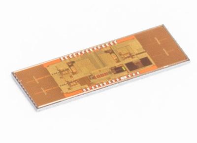
Figure 6: Small radar Sensor
Small radar chips have a wide range of applications in various industries due to their compact size, low power consumption, and high performance. Here are some examples of small radar chip applications:
Applications
Due to their compact size, low power consumption, and high performance, Small radar chips have a wide range of applications in various industries. Small radar chips have almost same applications as radar sensors:
How Does a Radar Chip Work?
Small radar chips work by transmitting a radio signal toward an object and then measuring the reflection of the signal that bounces back. The time delay between the transmission and reception of the signal is used to calculate the distance to the object, while the amplitude and phase of the reflected signal provide information about the object’s position, size, and shape. Here is a more detailed description of how a small radar chip works:
- Transmitting the signal: The radar chip sends out a short burst of radio waves, typically at a microwave frequency. The signal is emitted from an antenna, which can be integrated into the chip or connected externally.
- Reflection of the signal: The radio waves travel through the air until they encounter an object, at which point some of the signals are reflected back towards the radar chip.
- Receiving the reflected signal: The reflected signal is received by the same antenna that transmitted the original signal, and is then amplified and processed by the radar chip’s receiver circuitry.
- Measuring the time delay: The radar chip measures the time delay between the transmission and reception of the signal. This time delay is proportional to the distance between the radar chip and the object.
- Analyzing the reflected signal: The radar chip analyzes the amplitude and phase of the reflected signal to determine the position, size, and shape of the object. This information can be used to detect obstacles, measure distances, and track the movement of objects.
Small radar chips can also use different types of modulation schemes, such as frequency modulation or phase modulation, to encode information into the transmitted signal. This allows them to achieve higher resolution and accuracy in detecting and measuring objects. Additionally, small radar chips may have different types of antennas, such as patch antennas or horn antennas, depending on the specific requirements of the application.
Radar Chips Roadmap and Future
The future of small radar chips looks promising, with increasing demand for their use in a wide range of applications. Here are some potential developments that could shape the future of small radar chips:
- Advancements in miniaturization: Small radar chips are already quite small, but further advancements in miniaturization could enable even smaller and more compact designs. This would allow radar chips to be integrated into a wider range of devices and applications.
- Increased accuracy and resolution: As technology improves, small radar chips are likely to become even more accurate and offer higher resolution. This would enable more precise object detection and tracking, and could lead to new applications in fields such as healthcare, robotics, and aerospace.
- Integration with other sensors: Small radar chips can already be integrated with other sensors such as cameras, lidar, and ultrasonic sensors. In the future, we can expect to see even greater integration between these sensors, resulting in more comprehensive and accurate data for applications such as autonomous vehicles and robotics.
- Expansion of applications: Small radar chips are already used in a wide range of applications, and we can expect this trend to continue in the future. For example, small radar chips could be used for structural health monitoring of buildings, bridges, and other infrastructure, or for environmental monitoring and disaster response.
Radar Chips Overview
In this section for better understanding, we have surveyed some small radar chips from different companies. This survey gives us perspective on small radar chips in various ways and helps us to determine the best option for our needs.
Imec 140GHz Radar
Technology: CMOS
Operating Frequency: 140GHz
Chip Size:6.5 mm2
Power Consumption: 500mW
Applications: finger/hand gesture detection, health monitoring, smart buildings
Other features: on-chip antenna, low power consumption, good accuracy, extremely compact
Infineon XENSIV™ BGT60ATR24C
Technology: BiCMOS
Operating Frequency: 60GHz
Chip Size:125 mm2
Power Consumption: <1 mW in deep sleep mode
Operating Temperature: -40-105 °C
Applications: High resolution FMCW radars ; Radar frontend for gesture sensing ; High resolution FMCW radars, Short range sensing operations, Hidden sensing applications behind radome, Automotive
Other features: external antenna, low power consumption, good accuracy, compact, robust, thermal management
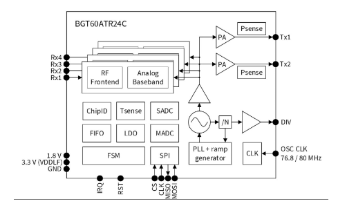
Figure 7: XENSIV™ BGT60ATR24C Block diagram
IWR6843AOP Texas instrument
Technology: RFCMOS
Operating Frequency: 60-64 GHz
Chip Size:22.5 mm2 FCBGA package
Power Consumption: max 1.75W
Operating Temperature: -40-105 °C
Applications: Industrial sensor, building automation, displacement sensing, gesture control, robotics, traffic monitoring, proximity and position sensing, security, motion detection, occupancy detection.
Other features: Antennas-on-package (AOP), FMCW transceiver, Built-in calibration and self-test, C674x DSP for advanced signal processing, Easy hardware design, Hardware accelerator for FFT, filtering, and CFAR processing, Arm-R4F microcontroller for object detection, and interface control.
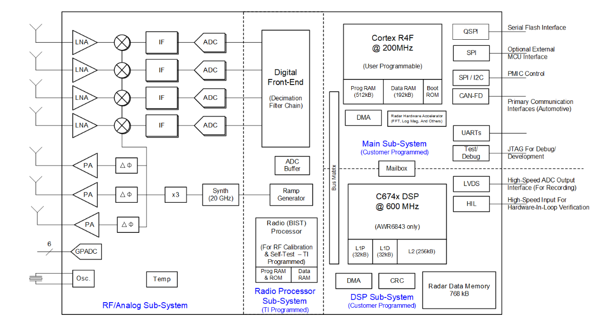
Figure 8:IWR6843AOP Block diagram
Acconeer A121 – Pulsed Coherent Radar
Technology: PCR
Operating Frequency: 60GHz
Chip Size: 29 mm2 FCCSP package
Power Consumption: –
Operating Temperature: -40-105 °C
Applications: gesture control, robotics, high accuracy proximity and distance sensing, motion and velocity detection, tracking, monitoring of vital life signs (like pulse rate), material detection.
Other features: High precision antennas-on-package (AOP), typical HPBW of 65 (H-plane), and 53 degrees (E-plane), without the requirement for a physical aperture, it is possible to embed it behind glass or plastic. It has an SPI interface for data transfer and supports SPI clocks up to 50 MHz. It is also possible to recognize motion and gestures for several objects.
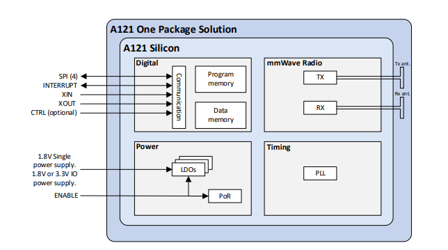
Figure 9: Acconeer A121 Block diagram
Read more about Acconeer 121 chip here
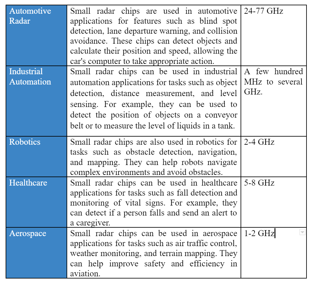
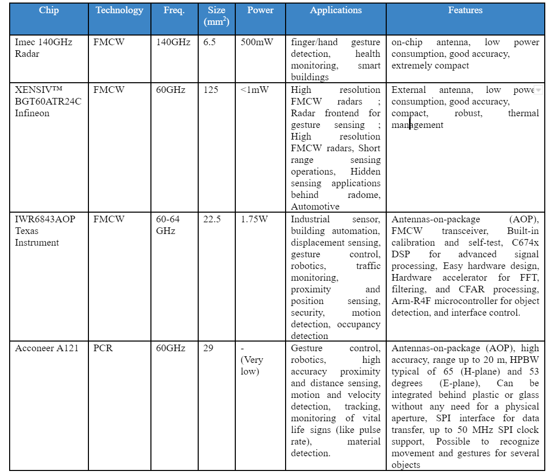
The following table presents a comparison and summary of radar sensor chips:
Conclusion
Imec 140GHz Radar, XENSIV™ BGT60ATR24C, IWR6843AOP from Texas Instruments, and Acconeer A121 are all small radar chips that are designed for different applications.
Overall, these small radar chips have different specifications and are designed for different applications. The Imec 140GHz Radar is still in development and has not yet been commercialized, while the other chips are available for purchase. It is important to choose a chip that is best suited for the specific application and requirements.


