This website uses cookies so that we can provide you with the best user experience possible. Cookie information is stored in your browser and performs functions such as recognising you when you return to our website and helping our team to understand which sections of the website you find most interesting and useful.
Introduction to Thyristors
25/05/2022, hardwarebee
Thyristor is one of the most common semiconductor device in electronics, mostly in high power applications. In fact, a thyristor is like a diode, but the main difference is that the thyristor can be controlled in the circuit. The control system only can turn on the thyristor by injecting current to the gate terminal, and there is no control on the turn-off condition. Hence, most principles of diodes are valid for thyristors can they have pretty similar applications such as AC to DC converter (rectifier), chopper, and so on. In this article, thyristor junctions are discussed first, and its principles and applications are presented comprehensively.
Semiconductor Types
There are two types of semiconductors, including p-type and n-type. Semiconductor components are a combination of these two semiconductor types, which create various features in each semiconductor component. The impurity in the n-type semiconductor is the electron, which means that the silicon or germanium in this type of semiconductor receives additional free electrons, and the semiconductor becomes negative. In contrast, in a p-type semiconductor, silicon or germanium loses electrons and produces a hole. As a matter of fact, holes are the place of lost electrons that are positive. Figure 1 shows these two types of semiconductors schematically.
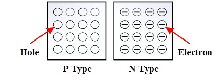
Figure 1: P-type and n-type semiconductors
These two semiconductors are quite conductive on their own because of excess electrons or holes in them. However, a combination of these two can create an interesting junction and provide new features. When they are put together, a junction is created, and electrons and holes can move in this p-n junction, as shown in Figure 2.
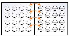
Figure 2: A sample p-n junction with holes and electrons migration in this junction
As the n-type and p-type semiconductors are neutral, elections migrations to the p-type semiconductor make it more negative, while moving holes to the n-type semiconductor make it more positive. This migration creates a region, namely the depletion region, in the p-n junction, which does not allow the current to flow through this junction even though the p-type and n-type semiconductors are conductive on their own, as shown in Figure 3. Basically, this p-n junction is a diode in which the current can flow through it only in one direction, and the thyristor is a developed version of the diode.
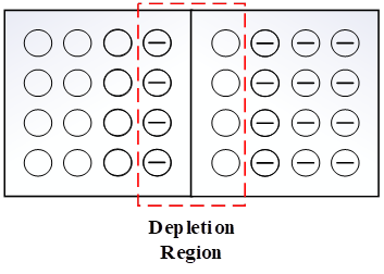
Figure 3: Depletion region in p-n junction
When a battery is connected to the p-n junction, according to Figure 4, the positive charges are forced to go through the p-type semiconductor to neutralize the excessive electrons in the depletion region. In contrast, the electrons from the negative side of the battery are forced to move through the n-type semiconductor to fill the missing electrons in the n-type semiconductor. In this situation, the depletion region becomes narrow, and the p-n junction becomes more conductive.
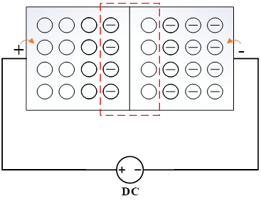
Figure 4: P-N junction behaviour when a dc voltage source like battery is connected to the junction
Thus, the p-n junction or diode can be conductive when the positive terminal of the battery is connected to the p-type semiconductor. Inversely, when the positive side of the battery is connected to an n-type semiconductor, as shown in Figure 5, more holes or positive charges are injected into the n-type semiconductor. Also, more negative charges are forced on the p-type semiconductor. In this situation, the depletion region gets wide and wider and prevents the current from flowing through the junction. Therefore, the p-n junction allows the current to flow in one direction as the diode works.
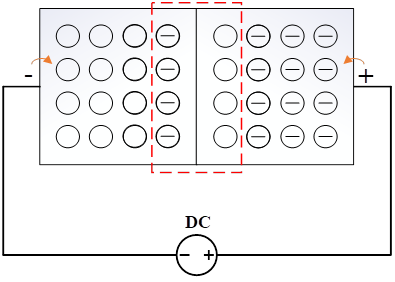
Figure 5: P-N junction behaviour when a dc voltage source like battery is connected to the junction
Thyristor Structure
As mentioned in the previous section, the diode consists of a p-n junction. The thyristor is similar to a diode, but there is an additional terminal which is called the gate to turn on the thyristor at a specific time. The thyristor symbol is illustrated in Figure 6, which has three terminals.
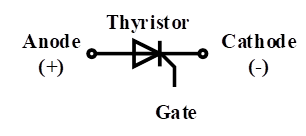
Figure 6: Thyristor symbol with three terminals including anode, cathode, and gate
To discuss the thyristor structure, its p-n junctions are presented in Figure 7. This component allows the current to flow through the circuit in forward bias and blocks the current in reverse bias like a diode. However, there is an additional blocking junction in the thyristor. When the battery is connected to the junctions in forward bias (positive terminal of the battery to anode), two p-n junctions start conductivity, but the middle junction is in inverse bias because the middle junction is an n-p junction which has a wide depletion region in this battery configuration. Therefore, the current cannot pass the thyristor in forward bias without a gate terminal. When a small positive voltage is applied to the gate, it actually reduces the depletion region of the middle junction and helps the thyristor to allow the current to flow. In fact, the gate is activated, and the current flows through the circuit to supply the load and the thyristor condition latches.

Figure 7: The thyristor p-n junctions
It means that the thyristor keeps its current condition until the thyristor a new condition happens. Thus, the thyristor cannot be turned off until the amount of flowing current from the anode terminal to the cathode terminal is considerably lower than the holding current of the thyristor or zero. The operation of thyristor is not fast, and most are used for low frequency and high-power applications.
Thyristor Gate Activation Circuit
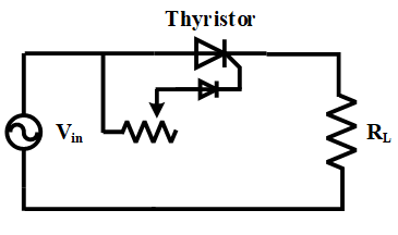
As mentioned before, thyristors can be used for low-frequency and high-power applications because this component is not very fast. One of the thyristor applications is AC to DC converters such as rectifiers. In some cases, the output DC voltage must be controlled according to the procedures. In this situation, the starting point of forward bias can be controlled by a gate signal. In fact, a part of the signal is chopped to decrease the output DC voltage. A common gate circuit is presented in Figure 8, in which the thyristor acts as a half-wave rectifier. It is worth noting that the thyristor circuit is not suitable for inductive loads due to many power factor issues.
Figure 8: A half-wave rectifier with thyristor and the gate activation circuit
The role of the diode is to ensure that only positive voltages enter the gate. In a positive half-cycle, the current will tend to flow through the circuit if the gate is activated. The gate current depends on the instantaneous voltage and the resistance in the series with the gate terminal. When the current goes beyond the thyristor holding current, the thyristor will go to the forward bias, and when the current passes the zero ampere, the thyristor will turn off. Figure 9 shows the output voltage of the thyristor half-wave rectifier, which has a lower DC voltage with respect to the same diode-based one because the thyristor gate chops a part of the waveform.
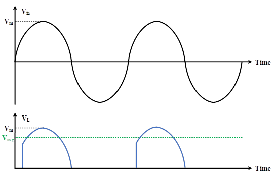
Figure 9: A thyristor-based half-wave rectifier waveforms
Thyristor V-I Curve
The current-voltage curve of the thyristor is similar to the diode, especially in reverse bias. However, the is a small difference in forward bias, as discussed in this article. The forward bias depends on the gate activation. Without activating the gate terminal, the voltage must reach to break the blocking junction, which can damage the thyristor. Therefore, the gate can be activated at any time before reaching the voltage to the mentioned voltage, and the current jumps to and above. The curve is presented in Figure 10.
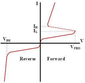
Figure 10 V-I curve for thyristor
Thyristor Advantages, Disadvantages, and Applications
Basically, the thyristor is a modified version of the diode which have some privileges with respect to the diode. The thyristor can be turned on easily and control alternative power. This component is quite inexpensive and can be used for high voltage and current applications. However, the thyristor cannot be used for high-frequency applications, and there is no control on turn-off condition. Totally, the switching speed is not high, and the gate current must be positive. Thyristors are mostly used in controlled rectifiers, inverters, and choppers. However, other applications are in variable speed motor drivers, welding machines, fault current limiters (FCLs), light dimmers, stabilizers, and everything that needs a controlled variable voltage or current. In the power systems, thyristors are widely in circuit breakers and HVDC systems.


