Ultimate Guide to: Electronic Circuit
31/05/2021, hardwarebee
Understanding electronic circuit is one of the most important and fundamental skill for any electronic engineer. It is essential for circuit design, implementation and debugging. Electronic circuit subject too extensive to be covered in only one article. Therefore, this tutorial is meant to be your first step towards this vast field, introducing you to the basic electronic circuit structures, elements, and devices, and how they behave electrically.
Electronic Circuit Overview
An electronic circuit schematic is nothing more than a visual representation of a mathematical model. This mathematical model describes how the real-life circuit works in electrical terms, and can be used to predict how signals will behave through the flow path. In a circuit schematic, each device is modelled by a different symbol, and each symbol is connected to other symbols via wires. Wires are represented by lines, also called branches, and are the first basic structure of a circuit. They are modelled as ideal conductors, which means that voltage is constant at any point of a branch. As wires connect to each other, we have the second basic structure: the node.
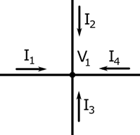
Figure 1: Node
Each node, and consequently all the wires connected to the node, have the same voltage. Thus, we can define a node by the voltage V1. Using Kirchhoff’s current law, the sum of the currents entering the node is zero. For the example in Figure 1, this translates to:
I1 + I2 + I3 + I4 = 0
The current travelling through an electric circuit must always return to its source. Therefore, every circuit is composed by one or more loops. Any closed path is called a loop, which is the third basic circuit structure. An example of a single loop is shown in Figure 2, where you can see that, differently from a node, there are several voltages.
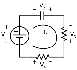
Figure 2: Closed Loop
The first voltage V1 is generated by a voltage source, and the voltages across the remaining elements are called voltage drops. According to the Kirchhoff’s voltage law, the sum of all voltages inside a loop should be zero:
V1 + V2 + V3 = 0
The Kirchhoff’s laws are the most basic tools for circuit analysis, giving rise to the so-called Nodal Analysis and Loop Analysis. The idea behind both techniques is to create an equation system using every node or every loop of a circuit, and then solving the equation to obtain all signals. Linear passive circuits can be easily solved using these methods.
Sources and Ground
Before we can talk about circuit components, we should define signal sources and ground. A signal source is a basic element that defines a fixed voltage on a node or a fixed current on a branch. Ideal voltage sources provide voltage differences between two nodes, with zero internal resistance. Ideal current sources, on the other hand, defines a current value of a branch, with infinite internal resistance. Finally, the ground is the reference point of a circuit, and is defined as the point where voltage is equals to zero.
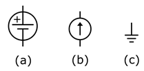
Figure 3: Voltage source (a), current source (b) and ground (c)
Linear and Passive Components
Linear systems are circuits that obey the linearity rules, which means (among other things) that the system function is not dependent on the magnitude of the input nor the number of input signals. Passive components are elements that do not require a power supply to properly operate. Resistors, capacitors, inductors, and transformers are the most common passive and linear components used in electronics.
Resistors
Resistors are two-pin passive components. They model the power dissipation caused by the electrical resistivity that is inherent in any type of material. The simplest example of electric circuit is a resistor in series with a voltage source, as shown in Figure 4.
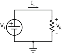
Figure 4: Resistor in series with a voltage source.
The resistor value defines the ratio between the voltage drop and the current in that branch, using Ohm’s law:

In the example of Figure 4, V1 and R are defined, and VR and I1 are the unknown variables. To solve them, we can use a simple Loop Analysis (Kirchhoff’s voltage law), that states:
V1 – Vr = 0
Vr = V1
Using Ohm’s Law to find I1:
V1 = R * I1
I1 = V1 / R
The same approach can be used to solve for different cases, such as a constant current sources or parallel/series combinations of resistors.
Capacitors
Capacitors are two-pin passive components capable of storing energy using the electric field between two metal plates. The ratio between the stored charge and the voltage is constant, and it is called capacitance (C).

For electronic analysis, electric current is more practical to use than charge. To include current in the model, we should derivate the equation in time, which results in:
dQ / dt = I
I = C * dV / dt
Here, is the time derivative of the voltage. For our scope here, it suffices to say that the variation rate of voltage is dependent on the current and inversely proportional to the capacitance. To properly solve this type of circuit, one should solve differential equations or use Laplace transformations.
We can draw some qualitative conclusions from this simple equation:
- If we force a constant current to a capacitor, the voltage will grow indefinitely.
- If we force a constant voltage to a capacitor, the current will be zero.
- If we force a sine voltage to a capacitor, the resulting current will be a cosine. In other words: the AC voltage generates an AC current 90° out of phase (leading).
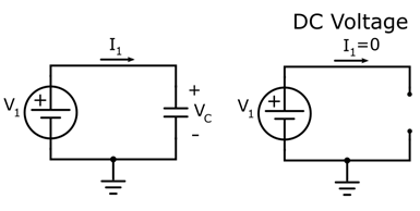
Figure 5: Capacitor in series with a DC voltage
Because of these properties, capacitors are widely used to block DC currents. For analytical purposes, the steady state of the circuit in Figure 5 can be modelled as an open circuit. The impedance of a capacitor, that is, the magnitude of the voltage drop for a given current, reduces with the frequency: for high frequencies, capacitors can be considered short circuits in some circumstances. However, this simplification does not always hold, and should be made carefully while considering the frequency range of the analysis.
Inductors
Inductors are two-pin passive components capable of storing energy using the magnetic field generated by an electric current. The ratio between the stored linked flux and the resulted current is called inductance (L).

Similar to the capacitance case, we need to modify the equation to obtain a relationship between voltage and current, which is more useful for electronic analysis. In this case, we replace the liked flux using Faraday’s law:
V = L * dl / dt
Here, is the time derivative of the current. This equation states that the variation rate of the inductor current is dependent on the voltage drop and inversely proportional to the inductance. Here are some interesting consequences:
- If we force a constant current to an inductor, the voltage will be zero.
- If we force a constant voltage to an inductor, the current will grow indefinitely.
- If we force a sine voltage to an inductor, the resulting current will be a cosine, which means that an AC voltage will generate an AC current 90° out of phase (lagging).
In practice, the inductor acts as a short circuit for DC voltages, and the impedance of an inductor increases with the frequency. This means that for very high frequencies, an inductor can be considered an open circuit. Similar to the capacitor case, this type of simplification should be made carefully.
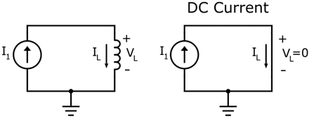
Figure 6: Inductor in series with a DC current source
Transformers
Using the properties of the inductor and the Faraday Law, one can tightly couple two coils magnetically, resulting in a transformer. Transformers are four-pin devices capable of multiplying a voltage or current applied to one side by a constant factor, which is defined by the ratio between the number of turns in each coil (N = N2/N1). The basic transformer is shown in Figure 7.
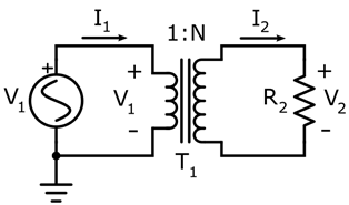
Figure 7: Basic transformer application.
Voltages V1 and V2 are related by the equation:
V2 = N * V1
Currents I1 and I2 are related by the equation:
I2 = I1 / N
These properties make the transformer a very useful device to amplify voltages or currents without needing active devices. Also, they provide galvanic isolation between the two-sides, which is very useful for safety purposes. They can be made very small for high-frequency applications and very large to handle power applications in low-frequencies.
One can also calculate an equivalent resistance seen by one side of the circuit. Take, for example, the circuit in Figure 7. The equivalent resistance seen by the left side can be calculated using Ohm’s Law:
Req= V1 / I1
The resistor R2 defines the ratio:
R2 = V2 / I2
Using the transformer equations, we can calculate the equivalent resistance:
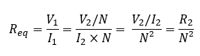
Therefore, we were able to change the equivalent resistance seen by the source V1 using a transformer. This property is the basic foundation of impedance matching in electronics.
Non-Linear Devices
Electronic circuits are not limited to linear elements. In fact, most integrated circuits are made purely of non-linear devices: the diodes and transistors. These devices have properties that depend on the value of the input, which breaks the rules of linearity. Therefore, to apply our previous approaches, we will need to define the operation mode of the device.
Diodes
Diodes are two-pin devices, made of PN junctions, with two modes of operation: reverse biased and forward biased. In the reverse biased operation (Figure 8a), the device acts like an open circuit, blocking any current (DC or AC). In the forward biased mode (Figure 8b), it has an exponential “Voltage vs Current” behavior, effectively acting as a constant voltage source with value VD (VD is the threshold voltage of the diode, with typical value of 0.7 V).
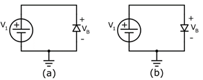
Figure 8: Diode reverse (a) and forward (b) biased
The mode of operation is defined by the voltage drop on the diode: if VB > VD, the device enters the forward biased mode; if VB < VD, the device enters the reverse biased. In practice, the diode allows current passing only in one direction, which is very useful for rectification.
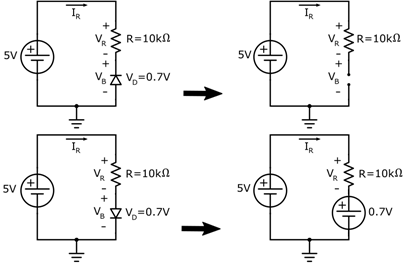
Figure 9: Diode in series with a resistor and the equivalent linear circuit (considering VD = 0.7V)
To exemplify, let’s solve the circuit of Figure 9. First, consider that the diode is reverse biased. In this case:
Ir = 0; Vb = 5V
Therefore, VB > VD, meaning that the diode should be forward biased, contradicting the first assumption. Now let us solve considering the diode is forward biased.
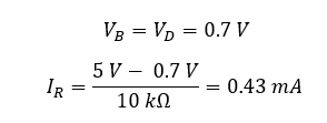
The direction of the resulted voltage confirms that the mode of operation is correct. Therefore, we successfully solved the circuit.
Transistors
Transistors are three-pin devices with several applications. They are the most used devices in electronics and the main components of an operational amplifier. Differently from the previous elements, transistors are active devices, which means that they need a power supply to operate properly. Although there are many types of transistors available (BJT, MOSFET, JFET), we are going to focus on the Bipolar-Junction Transistor (BJT). The BJT transistor has three pins: the collector, the base, and the emitter, and the voltage polarization between each one defines the mode of operation.

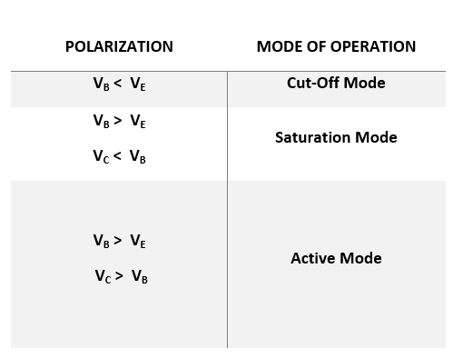
Figure 10: NPN (a) and PNP (b) transistors and their modes of operation
In real life, the base voltage VB must be bigger than the emitter voltage VE plus a threshold voltage VT, which is the threshold voltage of the base diode. Typically, this voltage is considered 0.7 V, because the base-emitter junction is basically a diode.
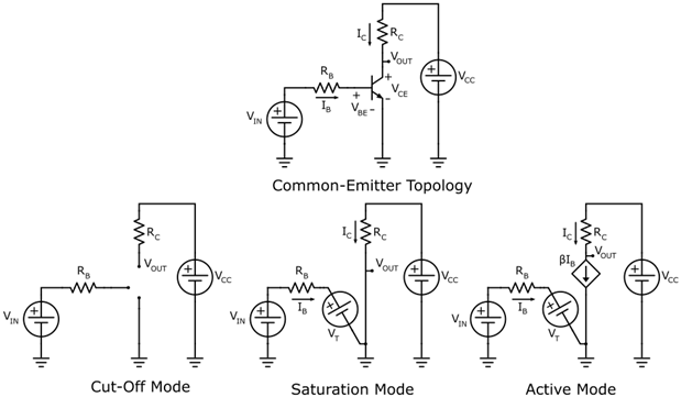
Figure 11: Common-emitter circuit using NPN transistor and the equivalent linear circuit for each mode of operation
It is easier to analyze a transistor using an example circuit. Figure 11 shows the common-emitter configuration, named that way because the emitter is connected to a known voltage. Using the simplified equivalent circuit, we can analyze the voltages and currents for each mode of operation:
- Cut-Off Mode: If VB < VE + VT and VC > VB, then the transistor is operating in cut-off mode. In this case, the circuit will work as an open circuit for both base and collector, and no current travels through its branches.
- Saturation Mode: If VB > VE + VT and VC < VB, the transistor is operating in saturation mode. In this case, the transistor will act as a forward biased diode from the base perspective and as a closed switch from the collector perspective.
- Active Mode: If VB > VE + VT and VC > VB, the transistor is operating in active mode. In this case, the transistor will act as a forward biased diode from the base perspective and as a current source from the collector perspective. The collector current is equal to the base current times a β factor: IC = βIB .
Because in both saturation and active modes the base acts as a forward biased diode, a resistor RB should be placed in series with the base to avoid a short-circuit. In practical applications, the cut-off and the saturation modes are typically used for logical switches. In this case, the transistor can be considered a voltage-controlled switch, and the common-emitter circuit acts as an inverter: when VIN is high, the switch closes and VOUT drops to zero; when VIN is low the switch opens and VOUT goes to VCC.
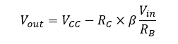
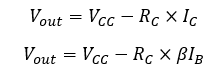
The active mode, on the other hand, is used to design amplifiers. As current is dependent only on the base current, we can design RB and RC to set the gain of a common-emitter amplifier. To calculate the DC output voltage, we can use the transistor equations:
IB can be calculated using the forward biased diode model:
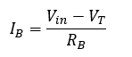
The voltage Vin is often much larger than VT, which is typically equal to 0.7 V. In these cases, we can simplify the analysis:
Finally, we can calculate VOUT: