
Ultimate Guide: Verilog Test Bench
18/04/2021, hardwarebee
This article is about how to write and use Verilog Test Benches. Designers that want to use Verilog as an HDL verification language for design and verification of their FPGA or ASIC designs. Verilog is an hardware description language used for the design and verification of the hardware design.
If you wish to take one step backwards, click here to read an introduction to FPGA test benches.
Verilog test benches are used for the verification of the digital hardware design. Verification is required to ensure the design meets the timing and functionality requirements.
Verilog Test benches are used to simulate and analyze designs without the need for any physical hardware or any hardware device. The most significant advantage of this is that you can inspect every signal /variable (reg, wire in Verilog) in the design. This certainly can be a time saver when you start writing the code or loading it onto the FPGA. In reality, only a few signals are taken out to the external pins. Though, you could not get this all for free. Firstly, you need to simulate your design; you must first write the design corresponding test benches. A test bench is, in fact, just another Verilog file, and this Verilog file or code you write as a testbench is not quite the same as the Verilog you write in your designs. Because Verilog design should be synthesizable according to your hardware meaning, but the Verilog testbench you write in a testbench does not need to be synthesizable because you will only simulate it.
Verilog Test Bench Examples
The following is an example to a Verilog code & Testbench to implement the following function in hardware:
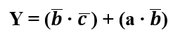
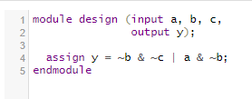
Verilog Code
Verilog Testbench
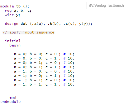
In the Verilog testbench, all the inputs become reg and output a wire. The Testbench simply instantiates the design under test (DUT). It applies a series of inputs. The outputs should be observed and compared by using a simulator program. The initial statement is similar to always; it starts once initially and does not repeat. The statements have to be blocking.
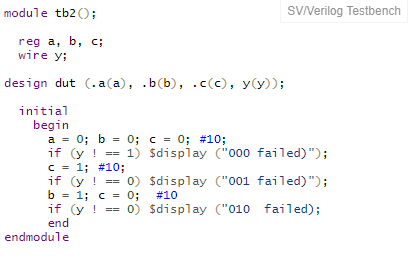
Self-checking Testbench
Self-checking test benches are better than regular Testbenchs; these test benches ensure the design’s functionality on their own. These kinds of Testbench also include a statement to check the current state $display will write a message in the simulator that will help the verification engineer see the design outcomes visually. The Self-Checking test benches effectiveness comes into play when you have a more significant design like a 32-bit processor, and you want to verify the outcome of the instruction, so rather than write a simple test bench, it is wise to use the self-checking Testbench to save time and verification cost.
Verilog Testbench Example – Self Checking
Testbench with Test Vectors
The more elaborated Testbench is to write the test vector file: inputs and expected outputs. Usually, it can use a high-level model name the golden model to produce the “correct” input-output vectors. The process for the Testbench with test vectors are straightforward:
- Generate clock for assigning inputs. A testbench clock is used to synchronize the available input and outputs. The same clock can be used for the DUT clock. So, both design and Testbench have the same frequency.
- Reading Outputs, Read test vectors file and put data into the array.
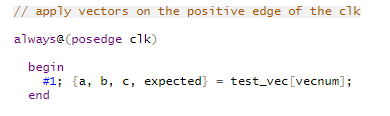
- Assign inputs, get expected outputs from DUT.
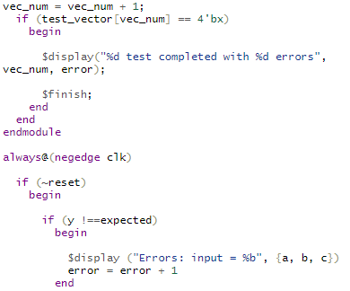
- Compare outputs to expected outputs and report errors.
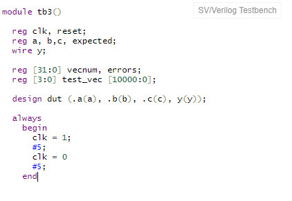
Verilog Testbench Example – Test Vector
File: example.v – contains vectors of abc_yexpected: 000_1 001_0 010_0 011_0 100_1 101_1 110_0 111_0 (file expected outputs).
Generate Clock
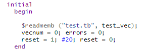
Read Test Vectors into Array
Assign Inputs and Expected Outputs
Compare Outputs with Expected Outputs
Initial / Always Blocks
Always and initial blocks are two main sequential control blocks that operate on reg types in a Verilog simulation. Each initial and always block executes concurrently in every module at the start of the simulation.
The Initial Block Example
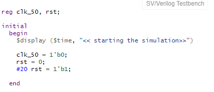
The initial block starts sequentially, displays the simulation’s time, and then sets the clk_50 to 0 and rst_1 to 0. And, after that, release the reset, and set it to 1 after 20 time period.
The always Block Example
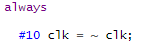
The always block runs every #10 ns starting at time index 0 ns. Therefore, the value of clk_50 will invert from the initialized value. This originates a clock pulse to be generated on clk_50 with a period of 20 ns or a frequency of 50 Mhz.
Delays
At the top of compiler directive: timescale 2 ns / 1000 ps is written.
This line is vital in a Verilog simulation because it sets up the timescale and operational precision for a design. It origins the unit delays to be in nanoseconds (ns) and the accuracy at which the simulator will round the procedures down to 1000 ps. This causes a #2 or #4 in a Verilog assignment to be a 2 ns or 4 ns delay, respectively.
Printing data during Simulations Runs
As a simulation runs, it’s significant to contain printout data to the screen to inform the designer on the position/ status of the existing simulation data. The value a net or register embraces at a particular time in the simulation may be imperative in debugging a function, so signals can also be printed. Two of the most mutual instructions to print to the screen are:
$display
$display is being used to print to a line and enter a carriage return (CR\r) at the end. The variables used to display the variables’ format can be: binary using %b, hex using %h, or decimal using %d.
$display(“Hello World!”);
mystring = “This is my string”;
$display(“mystring is %0s”, mystring);
$monitor
$monitor: The monitor precisely monitors the variables or signals in a simulation. Whenever one of the signals/variable changes value, a $monitor can be used to track it down. Only a single $monitor can be active simultaneously in a simulation, but it can prove to be a valued debugging tool.
$monitor (“format_string”, parameter_1, parameter_2, … );
$monitor(“x=%3b,y=%3d,z=%b \n”,x,y,z);
Tasks
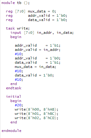
Tasks are used to group a set of repetitive or related commands that would typically be contained in an initial or permanently block. A task can have inputs, outputs, and inputs and can contain timing or delay elements.
This task code takes two eight-bit input vector, and at the positive edge of the next clock signal, it starts executing. It initially depends on the address, data and the mux input. The task block calls into the initial block call for three different inputs and performs the same operations on the different inputs.
Following are some recommendations that apply to all kind of simulation techniques as mentioned above:
- Initialize all the input ports at simulation time zero but do not initiate the expected stimulus for 100 (ns). The purpose is to hold off the input until set/reset has completed.
- The clock must be stable before applying the input data to the input ports.
- Output checking must be synchronized with the clock.


