Understanding Power Line Communication
03/10/2021, hardwarebee
Our world is now completely based on communication. Telecommunication terms that once were considered technical jargon, such as internet, Bluetooth, WiFi, 5G and IoT, are now a daily part of the common person vocabulary. In this context, there is a huge demand for various types of communication systems, including security, efficiency, data integrity and speed. However, the physical structure is still one of the most important factors, which defines many characteristics and limitations of a network. Therefore, one of the crucial steps in communication engineering is to answer the simple question: how do I transfer my data from A to B? Of course, the answer depends strongly on the application, data requirements, cost and, last but not least, convenience. And nothing is more convenient than a communication line that it’s already built. Therefore, Power Line Communication (PLC) is a communication system that uses power transmission lines to transfer data between devices supplied by the same network. In this article, you will learn about the main aspects of PLC, the types and standards applied around the world, the working principle and devices behind, as well as its pros and cons.
Basic Concepts
Power line communication works by injecting a carrier harmonic to the power line. This way, a receiver containing a filter tuned to this carrier can reject the intrinsic 50/60 Hz power line voltage and read only the transmitted carrier. This carrier can then be modulated to transmit information. Of course, the modulation type and parameters must be the same for both receiver and transmitter. Low frequency communications can be used to carry analog voice, telemetry and control signals, whereas high frequency PLC can be used to transmit digital signals at high bit-rates. Frequency ranges and applications are listed below:
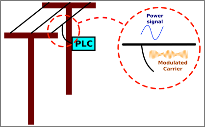
Figure 1: PLC injector installed in a power line
Low Frequency: 24kHz to 500 kHz
This frequency range is typically used for grid communications. Amplitude modulation is the common standard, allowing several channels to operate in the same line (though frequency discrimination). The signal itself can use only one cable or a combination of cables, and in some cases the ground path is used instead of the live wires. Grid communication can be applied in telemetry, automatic meter reading, fault prevention, monitoring and protection. Although these systems are not new, low frequency application is drawing more and more attention due to the arrival of smart grids: in these applications, local meters can send information to a control master via PLC, which makes a decision and sends command lines to devices able to control the grid.
Medium Frequency: 100 kHz to 1 MHz
These frequencies are used in applications that require faster transmission, but are limited by radio emitting standards. Therefore, frequency should be limited to avoid electromagnetic radiation from the power lines. They are applied in home control systems, using the already existing home wiring as a physical layer. The main advantage of this setup is that devices can be controlled through the same line that they are fed, so no extra wiring is required. If the device does not have a PLC interface, a converter can be used to read the PLC signal and yield a more suitable communication protocol. For instance, the figure below shows a home automation application of the medium frequency PLC. Narrowband signals can be used to acquire sensors and to transmit commands to home devices
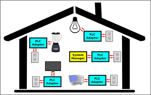
Figure 2: Indoors PLC configuration applied in home automation systems
High Frequency: higher than 1 MHz
These frequencies can be used to carry internet signals. For instance, using PLC/Ethernet adapters, a local area network (LAN) can be established inside a residence. Devices working with Ethernet plugs can be connected to these adapters, and the LAN signal flows through the residence wiring. This technique is a good option in offices and residences where wireless communication is limited or not available. In these applications, the HomePlug AV standard is the most applied technology. Internet communication between the power line and home appliances, as well as the communication between transformers, can also be performed. This method is called BPL, or Broad- band over Power Lines, and is the current standard for internet and high frequency transmission via public power lines. The figure below shows a residential network connected to the public power system via BPL.
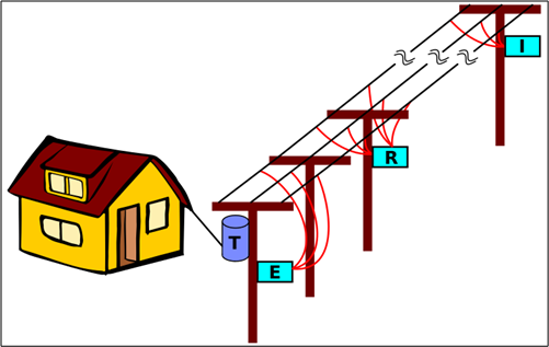
Figure 3: BPL transmission system. The injector I generates the transmission signal, repeater R is used to restore the signal, extractor E prevents the signal to be filtered by the low-voltage transformer T.
Components
The majority of expenses is dedicated to electronic components, as the transmission infrastructure already exists. Any communication system needs at least two components: the transmitter and the receiver. However, to maintain signal integrity, extra components, such as repeaters, filters and wave-traps, are required. The transmitter is responsible for injecting the signal to the power line, whereas the receiver reads the PLC signal. Both have similar setups: the transmitter have a frequency generator to modulate the signal, whereas the receiver can use a signal generator and an envelope detector to read the information; both have an interface with the power line to prevent high voltages to enter sensitive parts of the circuitry, and both devices need to perform signal processing and conversion. Figure 4 shows a simplified diagram of a general PLC transmitter and receiver.
Another major component is the line filter. This filter is responsible for rejecting all undesired frequencies from the power line (including the 50/60 Hz signal), and bypassing only the desired PLC. This is the main interface between devices and the power line, for both transmitters and receivers. For simple applications, dedicated decoupling capacitors are used in this stage. They provide high impedance for the power frequency, but allows a low impedance path for the carrier frequencies.
To prevent the communication signals to enter equipment through the power supply line and to allow signal sectionalization, a component called ”wave-trap”, or line-trap, is used. This component is made of different resonant circuits that provide high series impedance to the frequencies of the carriers, blocking all communication currents, while allowing power frequency to pass.
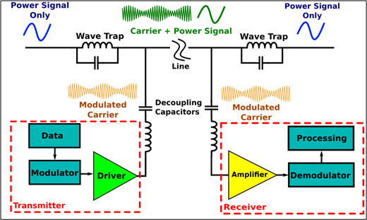
Figure 4: PLC basic components acting in a point-to-point communication. Decoupling capacitors provide interface and wave-traps provide line sectionalization.
Long PLC transmission suffers from considerable propagation losses. Therefore, one of the most critical components for long distance applications is the repeater. The repeater basically reads the desired signal from the PLC line, rejecting the power line frequency and unwanted signals, and injects a restored signal, with better amplitude and quality. Because propagation losses increase with frequency, the number of required repeaters also increase. Repeaters are also needed to pass the signal through transformers, that are optimized for power frequencies (50/60 Hz) and can degrade the transmitted signal.
Types of Power Line Communication
Although different protocols and legislation exists throughout the world, there are basically only types of PLC: the indoor PLC and the outdoor PLC.
- Indoor PLC: indoor PLC is used for LAN networking and narrowband in-house applications, such as home automation. It uses house power wiring to transmit data, injecting the current directly in the power plugs.
- Outdoor PLC: applied in the main power line transmissions, such as low frequency PLC (for telemetry and grid control), and in BPL, for internet transmission via power network. In this type of PLC, the equipment must be robust, to deal with the high voltage levels of the power lines. Also, as the information passes through the transformers, data should be kept viable, so repeaters are typically part of the
One classic example of outdoor PLC is ripple control, where an audio frequency tone is added to the AC line. The code transmitted using this tone can turn on and off devices at the client side. This resource is used to reduce power network loading during critical situations, preventing overloading and blackouts.
Power Line Communication Standards
There are two major standards for PLC: design specification and regulation for indoor data communication are provided by the IEEE 1901 standard, which is based on the HomePlug AV technology. On the other hand, for low frequency applications in power lines (grid communication), the major standard is the IEEE 1901.2, which regulates PLC for frequencies lower than 500 kHz.
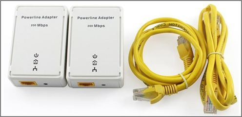
Figure 5: HomeAV compatible PLC to Ethernet Adapter.
Pros and Cons
The main advantage of PLC is obvious: the physical layer is already built and installed, so infrastructure costs are significantly reduced. Even in high frequency communication, data can be transferred between devices at the same building using only the power network and, depending on the desired range, some repeaters.
Power lines are not optimized for fast speed transmission, as power is typically transmitted at low frequencies (50/60 Hz). Therefore, signal propagation can be significantly limited in PLC, when compared to conventional transmission systems. The propagation limitation is frequency dependent: low frequency standards are able to cover larger areas of communication, whereas high speed communication is typically limited to local indoors networks. Besides the propagation issue, many regulatory agencies consider the transmission via unshielded lines equivalent to radio communication systems. Therefore, maximum frequency is tightly regulated in some countries.
Another disadvantage is that PLC operates in a half-duplex shared bus environment, so one bus is shared with many devices, including several ones that do not participate in the communication, which is a major limitation of the technology. All these devices inject broad frequency interference to the power line, which can degrade the communication significantly.
Conclusion
- PLC is the communication protocol that uses power line wires to transmit data;
- Because the power line infrastructure already exists, cost can be significantly reduced;
- Modern PLC is mainly used in telemetry and grid control, however internet transmission and home automation can use this method when convenient;
- PLC is regulated by the standard IEEE 1901, with the 2 regulating low frequency transmissions.
- Propagation losses are proportional to the frequency, so high frequency applications are limited and require more repeating stations;
- PLC operates in a half-duplex and shared bus Therefore performance is limited.


