
The Ultimate Guide to S Parameters
29/07/2023, hardwarebee
The linear characteristics of radio frequency (RF) networks, circuits, and components are described by scattering parameters (S-parameters). They measure the propagation of RF energy through a system and contain data on its essential properties, such as gain, loss, impedance, phase, and stability. S-parameters can be measured or saved in ordinary text files and used on any network at any frequency. S-parameters avoid the requirement to model an RF device’s internal features and instead concentrate on the input-versus-output behavior in several directions. They are complex integers that can be used directly or in a matrix to indicate frequency domain reflection/transmission characteristics (amplitude and optionally phase).
The S-parameter matrix may be used to determine the gain, loss, impedance, phase group delay, and voltage standing wave ratio (VSWR) of a linear network. To define S-parameters, we must measure the voltage and current at each network port. The S-parameters are then defined as the ratio of the incident wave to the reflected and transmitted waves at each port.
What are S-parameters?
S-parameters, also known as scattering parameters or scattering matrices, are widely used in RF (radio frequency) circuit analysis and design. They are a set of mathematical parameters that describe the behavior of electrical networks or devices at radio frequencies.
S-parameters are defined for multi-port networks, where each port represents an input or output connection. The S-parameters describe the relationship between the incident and reflected waves at each port. They are represented as complex numbers and are typically measured or calculated for a specific frequency or frequency range.
There are two types of S-parameters: forward and reverse. The forward S-parameters (S11, S21, and so on) describe the relationship between the incident wave at one port and the reflected and transmitted waves at other ports. The reverse S-parameters (S22, S12, and so on) define the relationship between an incident wave and reflected and transmitted waves at the same port.
Vector network analyzers (VNAs), which are specialized equipment for assessing the performance of RF and microwave devices, are commonly used to measure S-parameters. Typically, measurements are performed by injecting a signal into one port and measuring the corresponding signals at all other ports.
Engineers can match impedances, maximize power transmission, reduce reflections, and meet desired performance standards by modifying S-parameters. S-parameters are also used to anticipate circuit behavior before construction in simulations and models.
In summary, S-parameters are a collection of complex values that characterize the interaction between an incident and reflected waves at each RF circuit port. They are essential in RF circuit analysis, design, and optimization.
What will S-parameters Tell us?
S-parameters are useful for determining the behavior and characteristics of RF circuits. S-parameters can provide the following unique insights:
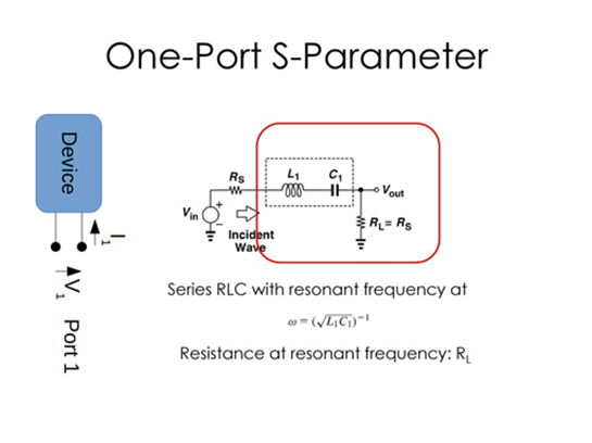
- Reflection Coefficient: S-parameters can be used to determine the amount of power reflected from a circuit or device. The S-parameters can be used to calculate the reflection coefficient (magnitude and phase) at each port, which indicates how well the circuit matches the impedance of the associated devices or transmission lines.
- Transmission properties: S-parameters characterize a circuit’s or device’s transmission properties. They represent how well the circuit carries power from one port to another, as well as the gain, loss, and phase shift at various frequencies.
- Frequency Response: S-parameters vary with frequency, allowing engineers to study a circuit’s behavior over a wide frequency range. They aid in the comprehension of frequency-dependent responses such as bandwidth, resonant frequencies, and the impact of parasitic elements.
- Signal Integrity: S-parameters are critical in determining the signal integrity of RF systems. They can indicate the presence of signal distortion, such as reflections, attenuation, and impedance mismatches, all of which can degrade the quality and integrity of sent or received signals.
- Impedance Matching: S-parameters allow engineers to evaluate RF circuit impedance matching. They can evaluate the degree of impedance match and change the circuit components accordingly to maximize power transfer by measuring the reflection coefficients.
- Network Analysis: S-parameters enable in-depth network analysis. The whole performance of a complicated RF system, including gain, phase shift, and frequency response, can be predicted by cascading S-parameter matrices of individual components.
- Design Optimization: S-parameters are employed in RF circuit design and optimization. Engineers can simulate and analyze various design configurations by adjusting the S-parameters, trying to accomplish desired performance standards such as increasing gain, minimizing reflections, or improving power transfer.
How can we Define S-parameters?
For multi-port electrical networks or devices, S-parameters, or scattering parameters, can be specified analytically. The size of the S-parameter matrix is determined by the number of network ports. S-parameters are defined as follows:
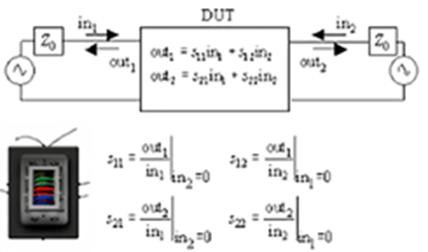
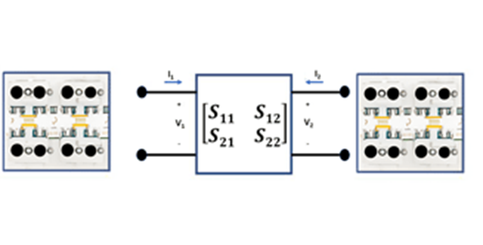
The S-parameters of an N-port network are represented by a N x N matrix. The matrix’s elements, abbreviated as Sij, depict the interaction between the incident wave at port j and the reflected and transmitted waves at port i.
Each S-parameter, Sij, is a complex number with two components: magnitude and phase. The magnitude of the reflected or transmitted wave is represented by the magnitude of the phase shift experienced by the wave.
S-parameters are further classified into two types:
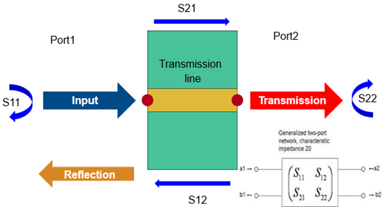
1. Forward S-parameters define the relationship between an incident wave at one port and reflected and transmitted waves at other ports. The forward S-parameters are indicated as Sij, where i j is an integer. S11, for example, denotes the reflection coefficient at port 1, S21, the transmission coefficient from port 1 to port 2, and so on.
2. Reverse S-parameters define the relationship between an incident wave at one port and reflected and transmitted waves at the same port. Sii represents the reverse S-parameters. S22, for example, denotes the reflection coefficient at port 2, S33, the reflection coefficient at port 3, and so on.
The S-parameter matrix can be written as:
S = [S11 S12 S13 … S1N] [S21 S22 S23 … S2N] [S31 S32 S33 … S3N] […] […] [SN1 SN2 SN3 … SNN]
In practical applications, S-parameters are measured or simulated for a specific frequency or frequency range. They provide valuable information about the performance of RF circuits, including reflection coefficients, transmission coefficients, gain, loss, and frequency response.
By manipulating and analyzing the S-parameters, engineers can evaluate and optimize the behavior of RF circuits, design impedance-matching networks, predict circuit performance, and assess signal integrity.
What are s-parameters Applications?
S-parameters, or scattering parameters, find extensive application in various areas of RF (radio frequency) circuit analysis, design, and characterization. Some of the key applications of S-parameters are:
- Network Analysis: S-parameters are used to analyze the behavior of RF networks or systems. By cascading S-parameter matrices of individual components, the overall performance of a complex network can be predicted, including gain, phase shift, frequency response, and impedance-matching.
- Circuit Design and Optimization: S-parameters play a crucial role in the design and optimization of RF circuits. Engineers can simulate and evaluate different circuit configurations using S-parameters to achieve desired performance specifications, such as maximizing gain, minimizing reflections, optimizing power transfer, and ensuring impedance matching.
- Impedance Matching: S-parameters enable engineers to assess and design impedance matching networks for RF circuits. By analyzing the reflection coefficients, they can determine the degree of impedance match and adjust circuit components to maximize power transfer between the source and load.
- Amplifier Design: S-parameters are used in the design of RF amplifiers to analyze gain, stability, and linearity. By examining the S-parameters of various amplifier stages, engineers can optimize the circuit for desired gain, bandwidth, and input/output matching.
- Filter Design: S-parameters are employed in the design and analysis of RF filters, such as low-pass, high-pass, band-pass, and band-stop filters. They help evaluate the filter’s frequency response, insertion loss, selectivity, and return loss.
- Antenna Analysis: S-parameters are used to assess the performance of antennas. By measuring or simulating the S-parameters of an antenna, engineers can evaluate parameters like return loss, radiation pattern, impedance matching, and antenna efficiency.
- Signal Integrity Analysis: S-parameters assist in evaluating the signal integrity of RF systems. They can identify issues such as reflections, attenuation, and impedance mismatches, which may affect the quality and integrity of transmitted or received signals.
- Interconnect Analysis: S-parameters are employed in the analysis of interconnects and transmission lines. They help evaluate signal integrity, impedance mismatches, crosstalk, and other effects in high-speed digital and RF communication systems.
- RF System Simulation: S-parameters are used in simulations and modeling to predict the behavior of RF systems before fabrication. They enable engineers to evaluate system performance, optimize component selection, and assess the impact of different system configurations.
How can we Calculate s-parameters of RF Circuit?
Calculating S-parameters for an RF circuit typically involves a combination of theoretical analysis and experimental measurement. Here is a general overview of the process:
- Theoretical Analysis: If you have a detailed circuit model or schematic, you can use theoretical analysis techniques to calculate S-parameters. This involves applying circuit theory, transmission line theory, and electromagnetic theory to derive the equations that describe the circuit behavior.
- Simulation: Utilize RF simulation software, such as ADS (Advanced Design System), Microwave Office, or SPICE-based simulators, to simulate the circuit and obtain S-parameter values. These tools use numerical algorithms to solve the circuit equations and calculate the S-parameters based on the circuit model.
- Network Analyzer Measurement: To obtain accurate S-parameter values for a physical circuit, you can use a vector network analyzer (VNA). A VNA is an instrument specifically designed for measuring the characteristics of RF circuits. By connecting the ports of the circuit to the VNA, it can sweep through a range of frequencies and measure the magnitude and phase of the reflected and transmitted waves. The VNA then calculates the S-parameters based on these measurements.
- De-embedding: In some cases, you may need to separate the S-parameters of a specific component or subsystem from the overall circuit. This process is known as de-embedding and involves measuring the S-parameters of individual components separately and subtracting their influence from the overall circuit measurement.
It is important to note that the complexity of the circuit, the accuracy requirements, and the available tools and resources will impact the method used to calculate the S-parameters. Theoretical analysis and simulation are often employed in the design phase, while network analyzer measurements are typically used for characterization and validation of fabricated circuits.
Additionally, it is worth mentioning that commercial RF component datasheets often provide S-parameter values measured by the manufacturer, which can be used as a reference or input for circuit simulations.
Calculating S-parameters accurately requires a solid understanding of RF circuit theory, experience with simulation tools, and access to appropriate measurement equipment.
How to Design S-parameters in RF Circuit?
Designing S-parameters for an RF circuit involves several steps, including circuit layout, simulation, and measurement. Here is a general approach to designing S-parameters in an RF circuit:
- Circuit Layout: Begin by designing the physical layout of the RF circuit. Consider the desired circuit topology, component placement, transmission lines, matching networks, and interconnects. Pay attention to impedance matching and signal integrity considerations to ensure proper circuit performance.
- Component Selection: Choose appropriate RF components, such as amplifiers, filters, mixers, and transmission lines, based on the circuit requirements. Consider factors such as frequency range, power handling, noise figure, and gain.
- Circuit Simulation: Utilize RF simulation software, such as ADS (Advanced Design System), Microwave Office, or SPICE-based simulators, to simulate the circuit’s behavior and obtain simulated S-parameters. This involves creating a circuit model in the simulation software and specifying component properties, interconnections, and other relevant parameters. The simulation software will then calculate the S-parameters based on the circuit model.
- Optimization: Iterate the circuit design by adjusting component values, lengths of transmission lines, or other parameters to optimize the desired circuit performance. Simulate and analyze the effects of these changes on the S-parameters, aiming to achieve desired characteristics such as gain, bandwidth, and impedance matching.
- Prototyping and Measurement: Once you have a design that meets your specifications through simulation, build a physical prototype of the circuit. Use a vector network analyzer (VNA) to measure the actual S-parameters of the prototype. Connect the ports of the circuit to the VNA, and it will sweep through a range of frequencies to measure the magnitude and phase of the reflected and transmitted waves, calculating the S-parameters based on these measurements.
- Validation and Refinement: Compare the measured S-parameters with the simulated ones. Identify any discrepancies and analyze the causes. If necessary, refine the circuit design, component selection, or layout based on the measurement results. Iterate the process until the measured and simulated S-parameters align to ensure accuracy and performance.
It is worth noting that designing RF circuits requires expertise in RF circuit theory, simulation tools, and access to appropriate measurement equipment. It is also common to consult application notes, reference designs, and relevant literature to gain insights into best practices and techniques specific to the target application or circuit type.
Remember that designing RF circuits is a complex task, and it often involves multiple iterations of simulation, optimization, and measurement. Experience and understanding of RF circuit design principles will be valuable in achieving desired circuit performance and accurate S-parameter characterization.


