
Dynamic Power
31/08/2021, hardwarebee
Power dissipation reduction is one of the most pressing issues in VLSI design nowadays. Power may be dissipated in two ways in digital CMOS circuits: maximum power and average power consumption. Peak power is a reliability issue that impacts the life and performance of semiconductors. Since of the resistance system’s high instantaneous flow rate, the effects of voltage reduction diminish a design’s efficiency because there is more access and delay in connection. Because of the high energy use, the device overheats, decreasing the cycle’s dependability and longevity. Noise margins are reduced, increasing the likelihood of jig and chip failure. Time-averaged power usage in typical CMOS digital circuits can be dynamic or static, as seen in Figure 1.
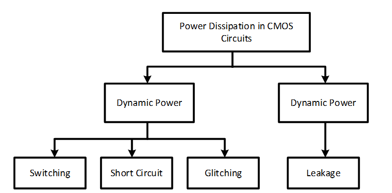
Figure 1: CMOS circuit different type of power dissipation
Dynamic power is the component of power dissipated in a CMOS circuit as the input varies from one level to another [1]. The majority of the power expended in circuits is dynamic power, which also contributes to peak power. The discharge of load capacitance accounts for the majority of dynamic power dissipation. For example, a chip may contain a large number of capacitive nodes, yet no dynamic power will be lost if the circuit does not switch. The following formula may be used to determine dynamic power:
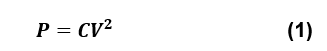
In the above equation P indicates the power, C is the capacitance and V represents the voltage.
Factors of Dynamic Power
Dynamic power depends upon the following factors:
- Peak power factor
- Switching frequency
- Supply voltage
Types of Dynamic Power
There are two types of dynamic power:
- Switching power is the current that flows from the source voltage to the output capacitance and back to the ground.
- Short circuit power occurs when current flows from the supply voltage to the ground when both NMOS and PMOS are active [1].
Dynamic Power Losses
Processor power losses are caused mainly by dynamic switching loss and static leakage loss. With operation frequency and the number of gates, dynamic losses increase. The loss of static leakage increases with a reduction in process geometry [2]. The combined dynamic and static power loss can be explained in a simple equation:
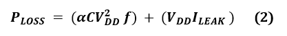
In equation 2, f represents the clock frequency, C is the capacitance, represents the effective percentage of gate switching.
The dynamic part of the power loss is attributable to the loading and unloading of each transistor and its corresponding capacity. The leakage of the power loss equation is mainly due to the leakage of the gates and channel of every transistor [2].
Dynamic Power in Circuits
The dynamic power is often used to build VLSI circuits. The dynamic capacity of a CMOS is calculated by combining its transient and capacitive load. The current that only flows when the device transistors transition from one logic state to the next is responsible for transient power consumption [3]. Transient power is defined as the power that flows only when the device’s transistors change from one logical state to another. This is due to the current required to load the internal nodes as well as the current itself.
The duration of the current spike is directly determined by the device’s frequency of changes, the increase/fall timings of the input signal, and the device’s internal nodes [4]. When the transition rate is high, the current of the door is less than the current of the switch. As a result, the integrated system’s internal capacitance, as well as the load and discharge current of the load capacities, regulate the dynamic supply current. This is because CMOS circuits spend a lot of power shifting charges in the condenser at the CMOS gates. Dynamic supply current is the most important.
A circuit consisting of several gates may therefore be viewed as a single big condenser loaded between the power supply rails and unloaded between them [4]. Temporary power can be measured:
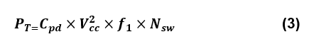
While Pt represents the supply voltage in equation 3 transient power, F1 displays the input frequency, Nsw shows the number of bits to switch, Cpd is the capability.
- Capacitive load power capacitance is charged with extra power and is affected by the frequency of the switch [4]. The capacitance load may be computed as follows:
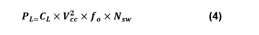
While PL is the capacitive load in Equation 4, Vcc is the delivery voltage, F0 displays the input frequency, Nsw is the output number, and Cpd is the capacity.
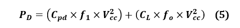
- Dynamic power is the summation of and can be expressed as:
Reducing Effects of Dynamic Power
Slowing down the design (reducing clock speeds), lowering voltages, or reducing design activity are all ways to preserve dynamic power. Another essential part of saving power is reducing capacitances in the design, which can usually be accomplished by efficient implementation or process modification [5].
References
[1] “Dynamic Power – AnySilicon Semipedia.” https://anysilicon.com/semipedia/dynamic-power/ (accessed Aug. 24, 2021).
[2] “Solve leakage and dynamic power loss | EE Times.” https://www.eetimes.com/solve-leakage-and-dynamic-power-loss/# (accessed Aug. 25, 2021).
[3] “An Introduction To Reducing Dynamic Power.” https://semiengineering.com/an-introduction-to-reducing-dynamic-power/ (accessed Aug. 25, 2021).
[4] Texas Instruments Incorporated, “CMOS Power Consumption and C pd Calculation,” Scaa035B, no. June, 1997, [Online]. Available: http://www.ti.com/lit/an/scaa035b/scaa035b.pdf%0Ahttp://scholar.google.com/scholar?hl=en&btnG=Search&q=intitle:CMOS+Power+Consumption+and+C+pd+Calculation#4.
[5] W.-K. Chen, “Electrical Engineering Handbook – 4. Introduction to Electric Machines,” Electr. Eng. Handb., pp. 721–736, 2005, Accessed: Aug. 25, 2021. [Online]. Available: http://app.knovel.com/hotlink/pdf/id:kt004KT2K1/electrical-engineering/introduction-electric.


