
Inductive Reactance Formula
17/12/2021, hardwarebee
This article covers the Inductive Reactance Formula topic, but before that, let’s start with an introduction to an inductor.
An inductor is a coil of wire wound around a central core. The magnetic flux (N) produced by a current (I) flowing through an inductor is proportional to the current flow (I). Figure 1 depicts the schematic symbol for an inductor. As seen below, the presence of continuous or dotted parallel lines close to the wire coil separates the various core types. Inductors are classified as hollow core (free air), solid iron core, or soft ferrite core depending on the sort of inner core they are wrapped around.
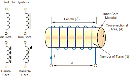
Figure 1: Inductor Symbols and wired inductor
Inductors oppose or obstruct variations in passing alternate current (AC), but they can readily pass a steady state direct current (DC). Inductance is the resistance to the rate of change of current flowing through an inductor due to the generation of self-induced energy inside its magnetic field. The effective resistance given by an inductor to the electric current passing through it is known as inductive reactance or inductive impedance.
Inductive Reactance
The reduction in current flow is defined as the effect of inductive reactance on the current flow of an alternating current in an inductor. Because of the inductance, any alternating current or changing current will be impeded.
Chokes and inductors are built up of wire loops or coils coiled around a ferromagnetic material or a hollow tube form to boost inductance. When voltage is applied across their terminals, inductors store energy in the form of a magnetic field. The back emf voltage of an inductor coil is determined by the rate of change of current flowing through it.
The current flow of an inductor with AC voltage differs from the current flow of an inductor with DC voltage. The phase mismatch between the voltage and current waveforms is caused by the sinusoidal supply. In an AC circuit, the opposition of current flow in the coil windings is determined by both the frequency of the waveform and the inductance of the coil.
AC resistance, also known as circuit impedance, determines the opposition of current flow across a coil in an alternating current circuit (Z). When separating DC resistance from AC resistance, the resistance is generally associated with DC circuits, and the standard term for this is reactance. Resistance and reactance are measured in ohms. The reactance value is denoted by ‘X’ to distinguish it from the resistive value.
The reactance of an inductor is termed inductive reactance since we are concentrating on the component inductor. It may be described as the electric resistance of an inductor when utilized in an AC circuit, to put it another way. Inductive reactance is denoted by the letter XL.
Inductive Reactance Formula
It is analogous to the resistance supplied by a resistor in the sense that both oppose the passage of electric charge. Electrons clashing with it when they travel through resistors, on the other hand, causes opposition. In an inductor, the self-induced electric magnetic field (emf) resists current rise and decay.
Consider the circuit below, which has an inductor and an AC voltage source (figure 2). As the quantity and direction of alternating current vary continuously, the inductor will generate an emf to resist any change in current passing through it.
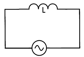
Figure 2: An indictor with AC source
We may represent this self-generated emf (V) using Faraday’s rule (which says that the voltage induced in a circuit is equal to the rate of change current traveling through the loop).
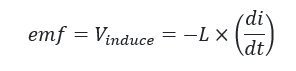
where:
L — Self-inductance;
di/dt — Rate of change of current across the inductor.
We may apply a modified version of Ohm’s law to get the average current (I) via the inductor.
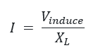
where the inductive reactance (XL.) is proportional to the AC signal’s frequency (f):
![]()
We may also compute the admittance (YL) or how readily current can pass through the circuit, as follows:
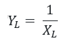
Unit of Inductive Reactance
To calculate the unit of inductive reactance, conduct a dimensional analysis of the formula for inductive reactance:
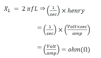
The dimensions of inductive reactance and resistance are the same, according to the dimensional analysis of the preceding formula. As a result, the inductive reactance is expressed in ohms (Ω).
We use the same unit for admittance as we use for conductance, namely the siemens (S).

The voltage and current are ninety degrees out of phase because the voltage is highest when the current change is greatest. This is an often-overlooked point. The voltage peak comes before the current peak in the cycle.
Current and induced voltage have a phase mismatch of 90 degrees, or pi/2 radians. As a result, with a perfect inductor, the current is 90 degrees behind the voltage.


