
IR Drop
02/09/2021, hardwarebee
The difference in electrical potential between the two endpoints of an electrical circuit during current flow is called IR drop. During the current flow, the voltage (V) falling across any resistance (R) is the product of current (I) and resistance (R). IR drop is sometimes referred to as the of Ohms Law and could be written as:
V = I * R
IR drop in circuit is due to several factors, such as a rush current, power straps, insufficient power supply, a high impedance of the power supply network and power supply network architecture, etc.
Types of IR Drop
Local and global IR drops are the two basic types of IR drop. When a group of gates, in close vicinity, switches at the same time, this is known as “local IR drop”. The term “global IR drop” refers to a phenomenon that happens when activity in one section of a chip causes an IR decrease in another section.
IR Drop Analysis
In IR drop analysis, the power supply in the device is distributed equally in all the metal layers across the complete design. These metal layers have a limited resistance, when a voltage is applied to these metal wires, currents begin to flow through the metal layers, and some voltage is lost as a result of metal wire resistance and current. For IR drop analysis, many tools are utilized, including Apache’s Redhawk and Cadence’s Voltage Storm.
Redhawk from Apache IR drop analysis is used at different stages of the design flow. When changes are costly and have little influence on the project’s timetable, it is preferable to employ Redhawk for IR drop analysis from the beginning of the design cycle. It can detect and correct through power grid design. This also decreases the number of adjustments needed in the sign-off step, where final static and dynamic voltage are conducted. As a result, Redhawk can be used at any point in the design process.
On the other hand, Voltage storm from Cadence used dynamic IR drop for analyzing the effect of transient drop. It helps in optimizing the number of decoupling capacitors to reduce leakage in circuit designs. Vector-based and vector fewer methods are used for measuring the consumption in voltage storm tools.
IR Drop Impacts
If the voltage drop is too high, the circuit will not have enough voltage, resulting in timing failure. If IR drop is increasing the clock skew then it will result in a hold time violation otherwise it will be a setup time violation.
IR Drop in ASIC Design
In ASIC design two types of IR drops are normally occurred i.e. static drop and dynamic drop.
Static IR drop is the average voltage drop for any given design. It is determined by the RC of the power grid that connects the power source to the appropriate standard cells [3]. Static IR decrease is denoted as:
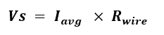
Dynamic IR drop refers to a voltage loss caused by the high switching activity of transistors. It is determined by the switching time of the logic and is less affected by the clock period. The formula for dynamic IR drop is:

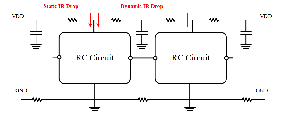
Figure 1: IR drop in ASIC Design
IR Drop in Semiconductors
Every transistor in a chip requires power. The metal layers are used to distribute the power around the microprocessor. The size of the wires has shrunk as fabrication processes have been reduced significantly, although the physical chip dimensions have remained nearly the same. The voltage is dropped when the current flows through a resistor, which is referred to as IR drop. When a transistor’s voltage lowers, it gets slower, which might affect circuit timing. This can lead to a functional failure if it occurs on a vital path in a design, hence it must be avoided. In Semiconductor design IR drop is a reduction in functional voltage, which means that small variations in supply voltage might account for a growing percentage of the digital swing, potentially resulting in inaccurate logic results.
IR Drop in PCB Design
Voltage is connected to the device pin via a plane or trace, which has resistance and is known as IR drop on PCBs. In this situation, the voltage will be lost due to the Ohm’s law. Energy is converted from electrical energy into thermal energy and the value for the voltage also decreases.
The PCB designer can use IR-drop analysis to detect if a plane has too many holes, if a trace is too narrow and lengthy, or if there isn’t enough bias. The voltage drop occurs in certain situations. A field solver may be used to determine the resistance, and a simulation can be used to see the results for current, voltage decrease, and temperature increase. Low resistance should be found in ground paths. The goal is to have as little power dissipation as possible. Each voltage drop generates heat, which could cause thermal concerns with nearby components. When the voltage drops too low, the supply voltage may fall below the supply voltage’s lower tolerance, causing the electrical components to fail. Power integrity is a crucial criterion in circuit designing which must be taken care of while designing any circuit. Figure 2 shows the IR drop analysis on PCB. The PCB designer can use IR drop analysis to detect if a plane has too many holes, if a trace is to narrow and too long or there are not enough vias placed.
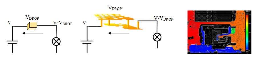
Figure 2: IR drop analysis on a PCB


