
Non Inverting Op Amp
31/08/2021, hardwarebee
Non Inverting Op Amp is a special topology of resistors and op-amps such that the gain is the positive multiple of the input voltage. In order to understand Non Inverting Op Amp topology, we need to first look at the operation principles of op-amps.
Op-amp General Information
Operational amplifiers (op-amps) are fundamental components that can perform mathematical operations such as summation, integration, differentiation as well as amplification (scalar multiplication). Moreover, Op-amps are also used in analog filtering applications, such as low pass filters (LPF), high pass filters (HPF) and band pass filters (BPF). With these versatile application fields, Op-amps are considered as fundamental building blocks with a rather easier to understand topology.
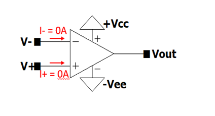
General equation Vout= A(V+-V–), where
- A: Open loop gain,
- V+: non-inverting input,
- V–: İnverting input
- +Vcc: Positive DC input
- -Vee: Negative DC input
- Rout = 0 ohm
- Rin (both for + in and -in) = infinity
Op-amps are 2 input-1 output circuit elements with 2 DC power input, one of which is +Vcc, a positive voltage supplied and the other -Vee, a negative voltage supplied. When V+=V–, the op-amp is said to be in “common-mode” and as it can be seen from the equation, common-mode output is zero (Vout= A(V+-V–)). However, when V+≠V–, the op-amp is said to be in differential mode or the input is “differential input”, so that output is now Vout = A(V+-V–).
No current is allowed to enter or exit from V+ and V–. V+ and V– are only used as voltage nodes. The reason is that input impedance of V+ and V- nodes are considered to be infinite for ideal op-amps. In addition, output impedance of Vout node is zero for ideal op-amps so that there are no losses at the output node and you get exactly A(V+-V–).
Closed loop gain is the gain you have (Vout/Vin) when op-amp input and output is connected each other through a resistor, or a capacitor or an inductor or any other circuitry. Open loop and closed loop gains are very different from each other. Open loop gain is a component feature whereas closed loop gain is a design feature that is related to how you structured your circuit, what kinds of resistances you put in the design and how you connected them.
In ideal op-amps, open loop gain A is considered to be infinite. In practical applications, open loop gain A is usually very big, in the order of 103 to 106, whereas closed loop gain is much smaller. Therefore, open loop gain A is considered to be infinite in most of the calculations. We will discuss when A should be considered as infinite and when shouldn’t. We will also investigate how to use A in calculations without assuming to be infinite.
Non Inverting Op Amp
Non-inverting Op-Amp configuration is where the closed loop gain (Vout/Vin) is positive such that the input is amplified with a positive scalar at the output. Figure 1 demonstrates non-inverting op-amp circuitry.
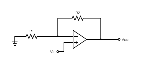
Figure 1: Non-inverting Op-amp Schematic
In order to understand if a circuit is non-inverting op-amp or not before calculating the closed loop gain is to check where the input voltage is connected to. For non-inverting op-amp configuration, input voltage is connected to V+ (non-inverting input) and the other terminal is grounded.
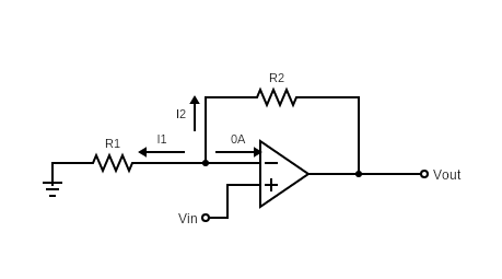
Figure 2: Non-Inverting op-amp with currents
As you can see from Figure 2, current entering or exiting V+ and V– inputs of op-amp are zero. This is an important characteristic of Op-amps that input nodes are voltage-only nodes because input resistance is infinite.
Also, open loop gain (A) can be taken into consideration or it can be neglected. For ideal Op-amps, open-loop gain is considered to be “infinite”. However, in practical applications, you need to compare open-loop gain with closed-loop gain (or voltage gain) and see if you can neglect it or not. Usually, open loop gain is 100 more times greater than closed loop gain, therefore it is neglected. We will further discuss later in this article how to decide when you need to take open loop gain as infinite in your calculations.
Closed Loop Gain
Closed loop gain by definition is the voltage gain, i.e., . Vout / Vin
Firstly, consider ideal op-amp case (that is, when open loop gain A is infinite). General equation is:
Vout= A(V+-V–), therefore V+-V–= Vout/A
![]()
Thus, V+= V– when A goes to infinity
For ideal Op-amps with infinite A, Vout/A goes to 0 as A goes to infinity. Hence, V+-V– = 0. In other words, if open loop gain is infinite, then non-inverting input voltage (V+) must be equal to the inverting input voltage (V–) (common-mode input). Therefore, we will always consider V+= V– when either the op-amp is ideal (A infinite) or when open loop gain is sufficiently large to be considered as ideal (we will later see what that means).
Therefore, in Figure 2 we get V+= V–= Vin since V+ is connected to the input voltage source.
At the node V+, we will apply Kirchhoff’s Current Law (KCL). KCL denotes that summation of all currents exiting a node is equal to zero.
KCL:
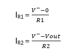
IR1 + IR2 + I– = 0, where IR1 , IR2 and I– are all exiting from V– node.
I– = 0
Replace IR1 , IR2 and I– In KCL equation, we get:
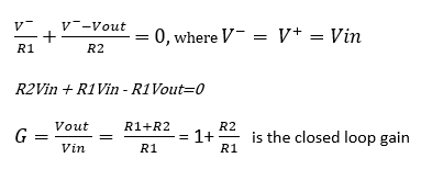
Note that R2/R1 ratio cannot be extremely big for 2 reasons. Firstly, using widely different resistances on the same circuit causes imbalance and practical problems in the system. Secondly, this topology has a frequency response too and using very high R2/R1 ratio actually reduces the bandwidth of the system. For a more robust design, keep the R2/R1 ratio at maximum of the order of 102.
Non-Ideal Op-amp Case
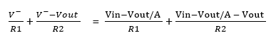
Now, consider open loop gain is finite. Our initial assumption of equating V– = V+ is no longer true for this case.
Vout= A(V+ – V–), where V+ = Vin (from Figure 2)
Vout = A.(Vin-V– ),
V– = Vin-Vout/A, where A is the open loop gain.
Now, replace in KCL equation above.
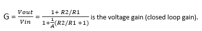
Rearranging the terms, you get:
How to Determine If Open Loop Gain Should be Neglected or Not
From the expression above, it is clear that when term is much smaller than 1, then this term can be neglected and G becomes 1+R2/R1, like we found in ideal op-amp case. Therefore,
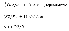
Hence, when A is much bigger than R2/R1, A (open loop gain) can be considered as infinity, op-amp can be treated as ideal op-amp and thus op-amp input voltages have to be equal to each other, i.e., V+ = V–
What Exactly is “Much Bigger” “>>”
If we consider R2/R1 to be in the order of 102, then A can be considered as infinite when it’s in the order of 104. Even if it’s in the order of 103, the effect will be very small. Depending on your purpose of implementation, you can take A as infinite when it’s 100 times bigger than R2/R1.
Let us calculate G when A is 10 times bigger than R2/R1.
Assume A=500 and R2/R1 = 50
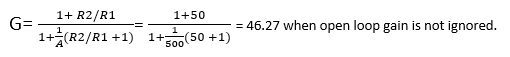
G = -1+R2/R1 = 51 when open loop gain is ignored.
Difference is less than 10%.
Depending on your application, you can determine what sort of error your circuitry can handle in your calculations.
Input Resistance
Input resistance is the resistance seen from input source. The input is connected to V+ terminal and the resistance seen from that terminal is infinity.
Output Resistance
Output resistance of the op-amp is zero as we know it already. However, there is a parallel branch (R2) to the op-amp. So, what’s the output resistance of this closed loop system? The answer is zero, because 0 resistance in parallel with R2 resistance is a short-circuit with equivalent resistance of zero.
Example Question
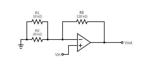
Assume the open loop gain of the op-amp above is 100. Calculate the power dissipated on R1 and compute Vout when Vin = 10V DC.
Solution
The equivalent resistance connected to the inverting input is R1//R2 = 10k.20k/30k = 20/3 kΩ
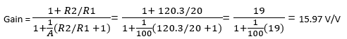
Vout = Gain.Vin = 15.97*10 = 159.7 Volts
Power dissipated on R1 is
First, let us consider the effect finite of open-loop gain.
Vout = A ( ), therefore 10 – 159.7/100 = 8.403 V
The voltage on R1 is = V- 0 = 8.403
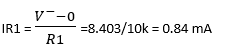
We get power P = 8.403.0.84mA = 7.05 mWatts dissipated on R1.
If we consider A >> R2/R1, therefore we take (infinite open loop gain).
The voltage on R1 is = V – 0 = Vin = 10V
The current passing through R1 is I
![]()
We get power P = 10V.1mA = 10 mWatts dissipated on R1.
As it can be seen from the proof above, the difference is very small in power calculation too because A is much bigger than R2/R1 ratio.


