
Pi Filter – The Ultimate Guide
30/10/2021, hardwarebee
Analog filters are some of the most fundamental and flexible structures in electrical engineering. They are used in impedance matching, harmonic oscillation, signal processing and control. However, the most common application is signal rejection. As explained in our previous article Introduction to Filter Circuits, filters are classified as active and passive filters. Active filters are powerful tools capable of recovering very small signals and rejecting the rest of undesired noise. Passive filters, on the other hand, may not be as powerful as their active counterparts, but they are definitely more efficient, as active filters require extra power to feed the circuit amplifiers. Therefore, passive filters are widely applied in power transmission and converting applications. In this article, we will discuss the Pi Filter, which is a topology of passive filter applied in ripple rejection for AC-DC voltage converters.
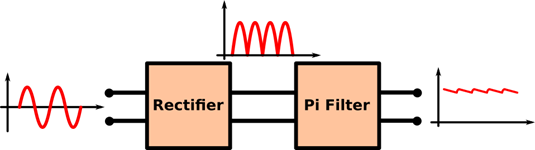
Figure 1: Pi Filter at the output of a rectifier
Pi Filter Working Principle
Before we approach the Pi Filter, let us take a look at two simpler filters: the shunt capacitor and the L-section filter. Both are applied at the output of voltage rectifiers (typically full-bridge topology, but it can also be used with half-wave rectifiers), which are used in AC to DC conversion. The shunt capacitor consists of a simple capacitor at the output of the rectifier, in parallel with the load. The capacitor absorbs the AC current from the source, but due to its energy storage capability the voltage is kept at the peak value, decreasing slowly as the energy is dissipated by the load, until the next peak is reached (Figure 2). In terms of impedance, it can be said that the capacitor provides a lower impedance path for the AC current compared to the load, and a lower AC current passing through the load means smaller AC voltage component.
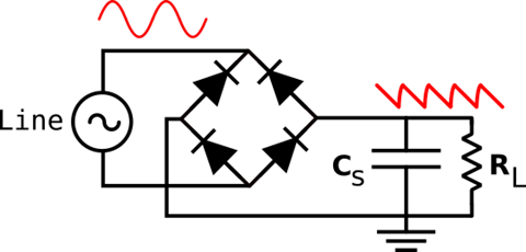
Figure 2: Shunt Capacitor Filter
This technique is extremely simple and effective, which explain its widely used in most applications. However, as you may have notice, there is one fundamental limitation to this approach: its effectiveness is dependent on the load. As the load demand increases, the speed of capacitor discharge increases and, consequently, the AC ripple increases. In applications with large load variation, the L-section is more adequate (Figure 3). This topology adds a choke inductor in series with a capacitor in parallel with the load, acting as a resonant second-order filter. If we consider only the choke inductor, it provides a high impedance path for AC current, with the effectiveness of the filtering process being directly proportional to the power demand: the smaller the resistance of the load, smaller is the AC ripple at the output. By adding a capacitor at the output, the L-section filter is lesser dependent on the load value, with the shunt capacitor acting on loads with larger resistance, and the inductor acting on loads with smaller resistance.
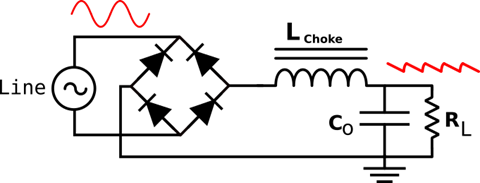
Figure 3: L-Section Filter
Although the L-section ripple is less dependent on the load, it still provides a ripple factor that is too large for some applications. If very low ripple factor is required, the Pi Filter is the right choice (Figure 4). It combines the shunt capacitor with the L-section filters to further reduce the voltage ripple. First, most of the AC component of the rectified voltage is absorbed by the shunt capacitor stage, which generate a DC voltage with large ripple factor. The L-section stage of the Pi filter acts on this ripple, further reducing the variation with the resonant filter. Also, because the L-section provides a high impedance path for AC current, the discharge of the shunt capacitor is very slow. All these effects combined result in very small ripple using only three passive components.
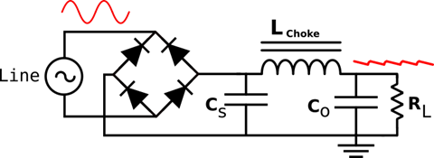
Figure 4: The Pi Filter
Types of Pi Filters
Low-Pass Filter
The name Pi filter comes from the shape of the Greek letter π, so any filter topology built around this shape can be called “Pi Filter”. In the previous section we approached low-pass Pi filter, which is commonly applied in the output of voltage rectifiers. Low-pass filters are responsible for rejecting high frequency content of signals while keeping a band of interest. In the power converter case, we are interested only in the DC component, so the low-pass cut-off frequency must be significantly below the line frequency. Another application of the low-pass topology is in signal reconstruction, where one can get the envelope of the modulated signal by using a low-pass Pi filter. The low-pass topology is composed of two capacitors and one resistor, as showed in Figure 5.
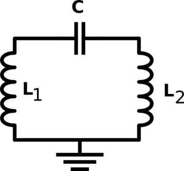
Figure 5: Low-Pass Pi Filter
High-Pass Filter
High-pass Pi filters are composed by two inductors and one capacitor (Figure 6). They are designed to reject small frequency signals from DC to a cut-off value. These filters are used in high-frequency RF applications, for signal modulation/demodulation, noise and EMI rejection, and impedance matching between the transmission line and antennae. In very high-frequency applications (GHz range) the Pi filter can be designed using only the PCB traces. High-pass Pi filters can also be used in analog sound processing, to reject DC currents (that can harm the speakers) or prevent Hum noise to reach the audio amplifiers.
Figure 6: High-Pass Pi Filter
Pi Filter Design
The design of Pi filters consists in simply finding the best values and types for each capacitor and inductor in the topology. However, the design process required depends on the application and type of filter implemented. Here in this article, we will discuss to cases: a low-pass filter for power converters and a high-pass filter for impedance matching. Keep in mind that different applications will require different approaches.
Low-Pass Pi filter for AC-DC power-converting
Although filters are typically designed using the cut-off frequency, Pi filters for power converter applications are designed considering the output voltage ripple. Voltage ripple for Pi filters can be calculated as follows:
Ripple = √2 /(8 ω3C1 C2 L RL)
Where ω is the line frequency in radians per second. The selected components should withstand the line voltage (capacitors) and the load current (inductors) without failing and reducing performance. Thick PCB traces are needed to provide a low resistance path to the high currents, and proper grounding techniques are mandatory.
High-pass Pi filter for Low Voltage Signal Rejection
First, using the design requirements, the engineer must select a cut-off frequency fC. This frequency depends on the minimum operating frequency and the desired rejection band. The cut-off frequency can be calculated as:
fC = 1/(4π√ (LC))
After selecting the cut-off frequency, both L and C should be designed to provide impedance matching for the circuit. If the characteristic impedance of the line is Z0, the capacitance and inductances are:
C = 1/(4π Z0 fC)
L = Z0 /(4π fC)
Practical design considerations are: minimize stray capacitances and stray inductances by proper manufacturing and component selection. Precise components are required because any mismatch can reduce performance.
Advantages and Disadvantages
The main advantage of the Pi filter is the extremely small voltage ripple using only simple passive components. The concepts behind the working principle are easy to grasp, even for non-engineers. Because only passive components are used, it withstands high voltages, which is fundamental for power systems applications. For low voltage applications, such as low-pass and high-pass RF filters, the Pi topology can be implemented using PCB traces, which is much easier to design, cheaper and robust than silicon-based filters.
However, because the DC voltage is largely dependent on the peak of the AC sine, voltage regulation is very poor, and the output DC voltage is highly dependent on the input AC. Also, passive inductors and capacitors for low frequencies (such as 50/60 Hz) and high voltages (power line) are big and bulky, which reflects directly in the large volume, weight and cost of these filters. Moreover, the load current is limited by the inductor capability, and large loads will consequently require bulky and expensive choke inductors. Finally, practical reactive components introduce losses to the system: both capacitors and inductor have parasitic resistances that consumes power, reducing the efficiency. Using well-designed capacitors and inductors with small ESR to increase efficiency will inevitably increase the cost.
Pi Filter Applications
- Low-Pass Pi Filters are widely applied in AC-DC power converters, specifically at the output of the rectifier to provide a smooth DC voltage from with small ripple factor. Stable DC voltages are fundamental for electronic applications, as any voltage ripple can be incorporated to the signal chain of the device. Moreover, Pi Filters can isolate the main lines from the high frequency switching currents generated by the switched-mode power converter (which is typically the next stage in an AC-DC converter), due to the high impedance of the choke at these frequencies.
- They are also used in high-frequency RF communication systems, where passive components can be easily implemented in PCB, providing a cheaper and more efficient solution than active filters. The Pi filter can be used in the low-pass and high-pass configuration, depending on the application, for modulation/demodulation, to reduce EMI, provide impedance matching and eliminating noise.
- Both high-pass and low-pass filters can be used in audio applications. Impedance matching with the speakers is extremely important to provide the best power transfer. Also, DC voltages can damage the speakers, so high-pass Pi filters can be used to reject any DC signal coming from the line. High-pass filters can also be used to reject the Hum noise, whereas low-pass filters can be used to reduce noise or to reshape the signal content of the device.


