
PWM Circuit
01/12/2021, hardwarebee
A PWM circuit is based on effective pulse width modulation technique that is used in power electronics to control signals of circuits. Although it is related to the field of communication systems (where it encodes amplitude of digital signals for transmission purposes), it is commonly used in electrical devices and AC/DC systems to control the amount of power supplied to them. Primarily, in the perspective of voltage, it works as a system to control the amount of power which is provided to an electrical device. It produces variable width pulses to show the amplitude of digital analog signals.
A PWM technique does not require Digital-to-Analog conversion because the noise is minimized by maintain signal as digital. Basically, in this technique the power or energy gets distributed via a series of pulses instead of variable analog signals. The flow of energy to the motor shaft can be controlled through an increase or decrease in pulse width.
PWM Circuit Duty Cycle
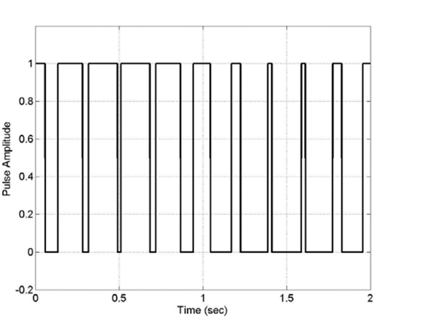
The proportion of ON time or the period of time when the pulse in High is termed as a “duty cycle”. Contrarily, when the power is low, it is referred to as low duty cycle as the flow of power remains stagnant or OFF for a duration of time.
It needs to be understood, that duty cycle of PWM is shown in percentage. Thus, in this sense, a duty cycle is considered 100% when it is fully ON. However, in scenario where a duty cycle of a signal is in ON-state for half of its total time and remains OFF during the other half of time, it is referred to as a duty cycle of 50%. digital signal is said to have a duty cycle of greater than 50%, if it remains in ON-state for a longer duration of time than its OFF-state. On the other hand, when a digital signal spends more time being off, it is described as a duty cycle which is less than 50%. Normally the PWM duty cycle can be represented using the following equation:
Types of PWM Circuits
Conventionally, there are three types of Pulse-Width modulation techniques. They are as follows:
Leading Edge Modulation
As suggested by its name, the lead edge or pulse center of the signal remains fixed while modulation happens in the trail edges. It is an easy to implement technique in which the PWM signal is turned off at the clock signal and then turned on when the error signal crosses the waveform ramp.
Trailing Edge Modulation
In this technique the trail edge remains fixed whereas the lead edge of the signal is modulated. Generally, the trailing edge modulation is used in the design of conventional and commercially available PWM converters.
Pulse Center Two Edge Modulation/Phase Correct PWM
The Pulse Centre Two Edge Modulation, which is also termed as Phase correct Modulation technique controls the duty cycle by fixating the center of PWM pulse while modulating both the trail edge and the lead edge. A main characteristic of this technique is that it permits the compression or expansion of the width of the signal wavelength as required.
The following figure illustrates the pulse width modulation techniques:
PWM Circuit Operation
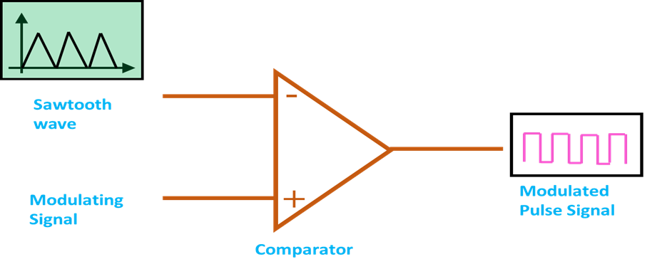
The operating principle of a Pulse Width Modulation technique can be explained in terms of generation of a PWM signal. The comparator is used in the generation of a PWM signal. The comparator has two input signals which includes a Modulating Signal and a Sawtooth Wave. At this stage the operation takes place at Carrier frequency. The comparator generates a PWM signal as output through a comparison of the above mentioned two signals.
If the value of modulation signal is lower than the Sawtooth Modulation signal than the PWM output signal is considered as “High” otherwise it is termed as “Low”. Therefore, the comparator output is determined via the value of magnitude of input signal. This, operation determines the width of the pulse produced at the output level.
PWM Circuit Applications
PWM circuit can be applied in various areas. Some of these fields are as follows:
- PWM techniques are commonly applied in the field of Telecommunication where they are primarily used for encoding purposes.
- A Pulse Width Modulation Technique facilitates in regulating voltage. Therefore, this particular application of PWM is visible in Smart Lighting Systems where it controls the brightness as well as increase or decrease the motor’s speed.
- A primary application of PWM is in computer motherboards. A PWM signal is used to control the amount of heat produced in the motherboard. For this purpose, a 4 Pin PWM header is embedded in the motherboard’s fan which expels the generated heart from the system and keeps it from overheating.
- A relatively wide application of PWM signals is in audio/video amplifier systems where it is employed to control the amplification of sound.
- They are also used in ROV applications. It helps to control and maintain the speed of DC motors.
Advantages and Disadvantages of PWM Circuit
The advantages of PWM are manifold. They are discussed as follows:
- An essential advantage of PWM technique is that it saves LEDs from overheating while maintaining the level of its brightness.
- It has a fast response time and provides accurate results.
- PWM technique has a Power factor which is high input.
- A primary advantage of PWM is that applying this technique requires quite low initial cost. Thus, it remains a cost-effective technique that can be used to control power level in electronic devices.
- This technique generates maximum torque by motors even if they are running at a low speed. Thus, it remains a popular method for DC motor control.
Where PWM has many advantages, it also poses a few limitations.
- Since the frequency of PWM is relatively high, it results in a high level of switching loss. This is considered as a major drawback of PWM.
- Radio Frequency Interference (RFI) is reduced in PWM technique.


