Adding a CPU to your FPGA Design – Tutorial
09/09/2019, hardwarebee
Adding a CPU soft core to your FPGA design is quite easy and explained in this tutorial. Embedded systems based on FPGA can today enjoy from a rich variety of CPU soft cores. This allows FPGA designers to partition their design implementation between software and hardware and accelerate the development of their embedded applications and add further flexibility to any FPGA design.
For example: serial\parallel interfaces can be implemented using the FPGA logic and the algorithms can be written in C/C++ language like any other computer program. Therefore, it’s very important to understand the benefits of adding a CPU to an FPGA design and decide, early on — which part of the FPGA design will be implemented by the logic fabric or by the embedded C\C+ code running on the CPU (microprocessor).
While FPGA is a great solution for hardware implementations of parallel processing, some designs are just easy to implement by software. Therefore, for some applications, the combination of both hardware programmability and software programmability could be of great value of: time to market, power consumption and development cost.
Essentially, there are two types of FPGA CPUs – (1) more powerful system-on-chip ARM-based, for example: Zynq-7000 family from Xilinx and (2) soft cores like MicroBlaze (Xilinx) or Nios II (Intel\Altera) that are implemented on fabric logic which offers lower performance. There are many other CPU soft cores on the market today that provide similar benefits.
In this tutorial we will look into building a microprocessor (CPU) system on an FPGA that controls on-board push-buttons/LEDs. Artix-7 50T FPGA Evaluation Kit from Xilinx and Vivado 2018.2 are used for this project with a soft core microprocessor MicroBlaze [1]. Our simple tutorial application toggles user LEDs one by one and changes direction of LEDs toggling when push-button is pressed.
Let’s start by creating a new project in Vivado 2018.2 tool: in the flow navigator run Create Block Design and add a MicroBlaze core, after pressing Run Block Automation, choose in debug module: Debug & UART.
This allows us to use the console build in Eclipse IDE SDK for debugging and communication with the MicroBlaze soft core processor.
You can download all the source files in this link.
It’s very convenient to use the board definition files of Artix-7 50T FPGA Evaluation Kit for adding different kind of peripherals of the board [2]. For example, we can add clock, reset, LEDs and push-buttons. After Run Block Automation and validation steps, our embedded system will look like this:
The system includes the following IP blocks:
– Clocking Wizard that implements a Digital Clock Manager for controlling clocks for CPU and peripherals [3];
– Processor System Reset for synchronous \ asynchronous reset of MicroBlaze and peripherals;
– MicroBlaze Debug Module for debugging and communication to soft microprocessor;
– MicroBlaze local memory;
– AXI BRAM Controller for BRAM Memory;
– AXI Interconnect for connection all peripheral through AMBA AXI4 protocol [4];
– AXI GPIO where is push-buttons and LEDs are implemented;
– MicroBlaze soft core.
The MicroBlaze soft microprocessor has a RISC based architecture. All the peripherals and the memory-based IP cores are as follows:
In our case AXI GPIO has address 0x41400000, Debug Module at 0x40000000 and AXI BRAM controller at 0xC0000000. This means that these addresses will be used for read\write registers from the IP cores by MicroBlaze.
We need to create a Verilog wrapper for our system before launching the Synthesis step, after that Synthesis, and Implementation and Generate bitstream steps are required. After writing they bitstream into our embedded system we are ready to go further – to develop the embedded application.
IDE SDK based on Eclipse IDE is designed for developing MicroBlaze’s embedded application and before launching one, we have to export our hardware platform including bitstream file into SDK (File – Export –Export Including Bitstream) [5].
Now, we can start a new empty Application project for standalone OS in IDE SDK. Our embedded application can run on FreeRTOS or Linux OS.
Three main directories will be created:
my_system_wrapper_hw_platform_0 – consists of .bit files for programming FPGA fabric logic;
leds_blinking_bsp – board support package with low drivers for all IP cores included in our project;
leds_blinking – directory where is our embedded code written in C\C++ and executable link file .elf are situated.
There are two main files in the last directory: lscript.ld and main.c. First one describes mapping of executable part of embedded application.
In our case it’s a BRAM memory mapped at 0xC0000000 address. The MicroBlaze starts program execution from the local memory and then goes to BRAM.
The second one consists of a program using Embedded C language. The program code is described below:
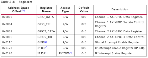
Our embedded application toggles user LEDS one by one and changes direction of LEDs toggling when pushbutton is pressed. We perform write and read operations through registers of AXI CPIO IP core. The AXI GPIO IP core’s product guide consists of registers space [6] as showed in the table below:
We use two main registers: GPIO_DATA (offset 0x0000) and GPIO2_DATA (offset 0x0008). The registers are used to write to and read from the general-purpose input\output ports. The first channel is used for push-buttons and set for inputs and second channel is used for user LEDs and set for outputs. We have to use offset 0x0008 for reading from user LEDs. We can use the Xil_8In \ Xil_8Out functions for accessing to register space. And we have to point base address of IP core’s registers we are going to use. In our case XPAR_AXI_GPIO_0_BASEADDR defines the base address of AXI GPIO IP core. This definition can be found in xparameters.h header that consists of our hardware system address details.
After compiling the program, we will get an executable link file with binary code of our program. Before launching one we have to download the hardware platform into FPGA. This can be done by downloading the bitstream that was generated after the Implement step in Vivado IDE. After downloading the bitstream and launching the .elf file we will get the following message in SDK IDE console:
Now, our embedded application starts. We can press any push-button and watch how the LEDs are toggling and the direction is changed.
Debugging of the embedded application is performed by the Xilinx System Debugger. We can run now the Debug Configuration and launch our application with several desired breakpoints.
By using the debug perspective, we can access to registers in the memory space of the MicroBlaze microprocessor.
Soft microprocessors are a very important part of any embedded system based FPGA. By adding one (or several) we can get functionality of microcontroller with custom low level drivers\cores\algorithms writing in HDL language. Debugging and developing embedded application by using Embedded C\C++ is easier and faster than the same algorithms writing in HDL. It’s very important to decide which part of the desired application in the embedded system can be done by using microprocessor and which part – directly in FPGA by HDL. In this case, part of embedded application development can be done by C\C++ programmer without any knowledge of HDL.
References:
- http://zedboard.org/sites/default/files/documentations/Installing-Board-Definition-Files_v1_0.pdf
- https://www.xilinx.com/products/intellectual-property/dcm_module.html
- https://www.xilinx.com/products/intellectual-property/axi.html
- https://www.xilinx.com/support/documentation/ip_documentation/axi_gpio/v2_0/pg144-axi-gpio.pdf


