Understanding Delta Modulation
07/08/2022, hardwarebee
What is delta modulation?
In the digital era, analog and digital signals are be converted into each other form. For this purpose, many techniques have been developed, which each of them has pros and cons. One of the techniques that are used for converting analog signals to digital signals or vice versa is delta modulation (Delta Modulation). In fact, Delta Modulation is a version of differential pulse-code modulation (DPCM) which is somehow the simplest version of it. In pulse-code modulation (PCM), the signal is modulated by taking all samples, and all of them are encoded by PCM, which increases the bandwidth. Besides, in DPCM, the difference of samples is encoded to overcome the described problem in PCM. By moving from PCM to DPCM, the bandwidth decreases, which can be much beneficial. In DPCM, the difference between two consecutive samples is considered as an error function, and this value is very small when the signal changes slowly in two consecutive samples. The situation is the same as the Delta Modulation is a special form of DPCM that employs an error function with only 2 levels in quantization. In this technique, the value of each sample is compared with the previous sample value, which can be higher or lower than the present value. It should be noted that the step size is fixed in this method. Considering l levels of quantization and n number of bits of the encoder, it can be written:
(1)
![]()
For delta modulation as l is equal to 2, n is 1 which means that 1 bit encoder can be explained for this technique, either 0 or 1. By reducing n, the BW is decreased because it is equal to nfs which is fs in this type of modulation.
Block diagram of delta modulation and explanation
In this modulation approach, if the input signal x(t) is greater than the quantized signal x(t) , the error function will be positive. In contrast, when the input signal is less than the quantized signal, the error function will be negative. Therefore, these criteria can be written as:
(2)

where step size is represented as Δ.
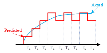
For better understanding, the presented analog signal in Figure 1 is used as a sample. The purpose is to modulate the signal by the Delta Modulation. The input sample is the instant value of the signal in each sampling time, and the predicted value is defined in each step based on Equation 2. At the starting point, since there is no predicted value, 1 step size is added. In the next step, the step size value must be compared with the actual value of the signal. As the actual value is greater than the quantized sample, another step size is added up. This process is continued to the end of the signal. As can be seen, after four steps, the predicted value goes higher than the actual value, and 1 step size must be subtracted according to the mentioned equation. The step size in this method is fixed, which can cause some issues in some cases. In fact, positive step size can be denoted by 1, and negative step size is represented by 0.

Figure 1: Delta modulation technique for converting an analog signal to digital with D step size and Ts time interval
To build the block diagram of the Delta Modulation, the error function is defined at first, which is the actual value subtracted by the predicted value of the signal. This error function is sent to 2 levels quantizer (1-bit quantizer). In the feedback branch, there is a delay that is connected to the predicted value, and it is added to the quantized error, as shown in Figure 2. The previous predicted value is restored by delaying one period in the feedback loop. Finally, an encoder makes a decision about the binary value corresponding to the error function as 0 or 1. When the result is 1, the approximate value goes up, and inversely when it is 0, the predicted value decreases. Thus, the step size can be written as:
(3)

where syn is the sign function which can accept -1, 0, and +1 based on the input value (error value) sign.

Figure 2: A simple block diagram of delta modulation technique
Applications of the Delta Modulation technique
Generally, the Delta Modulation method is used where the signal quality has low importance, as it is the simplest version of DPCM, and it does not have a significant accuracy, especially when signal changes are too high or near zero. Thus, this method can be used in radio communication devices and digital transmission of the voice. Storing voice is another application of the Delta Modulation. It also can be used in television systems. Controlling the inverters is also possible with the Delta Modulation technique, as they need the simplicity of the implementation and modification of the control parameters. This technique is applicable for all series connected inverters with various levels. As mentioned, the Delta Modulation can be used for transferring and storing data, which is useful for electroencephalogram (EEG) analysis for a large volume of digital data and demanding processing tasks.
Advantages of the Delta Modulation Technique
As described in this article, the Delta Modulation has a low BW requirement, and it is relatively simple and inexpensive because there is only one 2-levels quantizer in the block diagram. Moreover, the step size is fixed, and there is no need to change it. Also, the encoder must only make a decision between 0 and 1 to determine the direction of modulation. In this technique, there is no analog to digital converter, which simplifies the modulation.
Delta modulation has several advantages, including:
- Simplicity: Delta modulation is a relatively simple ADC technique that requires minimal hardware complexity.
- Low cost: Delta modulation requires fewer components than other ADC techniques, making it more cost-effective.
- High accuracy: Delta modulation can provide high accuracy compared to other ADC techniques, especially when the signal to be converted is relatively stable.
- Robustness: Delta modulation is relatively robust and can handle noise and interference well.
- Low power consumption: Delta modulation requires low power consumption, making it suitable for use in battery-powered devices.
- High data rate: Delta modulation can support high data rates, making it suitable for use in high-speed communication systems.
Disadvantages of the Delta Modulation Technique
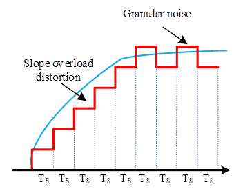
The presented technique has two drawbacks, including slope overload distortion and granular noise. These two important disadvantages are owing to the fixed step size in the Delta Modulation method. The slope overload distortion happens when the signal changes rapidly and the slop is high. In this condition, the Delta Modulation method adds or subtracts a fixed step size value and cannot be close to the actual signal, which produces considerable errors in transmission. The following criterion expresses the condition for slope overload distortion.
(4)

The second drawback is for the low slope part of signal when the step size is added and subtracted consecutively like a noise, shown in Figure 3. The criterion for granular noise is:
(5)

Apart from the two mentioned issues in the Delta Modulation technique, having a predictor makes the technique complex, and it does not have a good start-up response.

Figure 3: Slope overload distortion and granular noise in delta modulation technique which causes problems for this method.
Limitation of Delta Modulation
Some limitations of delta modulation include:
- Limited dynamic range: Delta modulation has a limited dynamic range, which means it is not suitable for encoding signals with large amplitude variations.
- Limited resolution: The resolution of delta modulation is limited by the size of the reference signal step, which means it may not be suitable for encoding high-resolution signals.
- Quantization noise: Delta modulation introduces quantization noise, which is the difference between the encoded signal and the original signal. This noise can be reduced by increasing the reference signal step size, but this also reduces the resolution of the encoded signal.
- Complex decoding: Delta modulation requires complex decoding algorithms, which can make it more difficult to implement compared to other analog-to-digital conversion techniques.
- Sensitive to errors: Delta modulation is sensitive to errors in the reference signal, which can result in errors in the encoded signal. This can be mitigated by using error correction techniques, but this also increases the complexity of the decoding process.
Adaptive Delta Modulation
The mentioned disadvantages of the Delta Modulation need to be solved. The reason is the fixed value of step size, and it can be solved by presenting an adaptive delta modulation (ADelta Modulation) to overcome the issues. The concept is that the step size would be adapted to the message signal. If the slope is high, the step size must increase to follow the actual values, and if it is low, the step size must be reduced. The step size can vary in two manners, including continuous variation and discrete variation in the step size. To change the step size, a logic controller is required to detect the slope and determine the relative step size in time intervals. In fact, the principles of Delta Modulation and ADelta Modulation are the same, and the only difference is the logic control for ADelta Modulation. All in all, the ADelta Modulation reduces the slope error in the Delta Modulation and improves the signal-to-noise ratio, which is a critical factor for modulation techniques. Moreover, signals with a high dynamic range can be transmitted by this method as the step size changes with respect to the message signal slope. In discrete ADelta Modulation, the step size determination logic is that each step size is defined based on the previous step size and the difference between actual and predicted values. When the predicted value is below the message signal, one step size is added to the last step size to increase the variation rate, but when it is above the actual value, one step size is subtracted from the last determined step size to reduce the variation rate. Although the ADelta Modulation acts as a low pass filter to reduce the quantized noise, this noise is still available and can cause some problems.


