Difference between Synchronous and Asynchronous Counter
04/06/2022, hardwarebee
Synchronous and asynchronous counters are the two widely used counters in digital circuits. In this article, the difference between synchronous and asynchronous counter are discussed in detail including their characteristics, applications and operation are meticulously written.
Counters are the simplest form of sequential circuits and flip-flops are the basic building blocks of sequential circuits. Flip-flops are connected together to form counters. Apart from counting, counters can be used to measure some fundamental quantities like time, frequency, memory addresses etc.
In this article we will use an example of a three-bit binary counter to discuss the difference between synchronous and asynchronous counter . This is a binary counter, and it is capable of counting in binary sequence (that is 1’s and 0’s). It is capable of counting from 000)2 to 111)2. This counter resets itself and back to 000)2 when it is reached to the maximum count. For an ‘N’-bit counter, ‘N’ number of flip-flops are required, and hence it is capable of counting up to 2N-1. For example, an 8 bit binary counter has 8 flip-flops and can count up to 28 – 1 = 256 – 1 = 255. Or in binary format, it can count from 00000000)2 to 11111111)2 and then reset. Designing an N-bit counter is easy — just add a flip-flop for every additional stage.
Asynchronous Counters
These counters are made up of a series of flip flops that are connected in series or back to back. The clock is applied to the first flip flop only. The second flip-flop is triggered by the transition that occurs at the output of the first flip-flop. Similarly, the clock input of the third flip-flop is triggered by the output of the second flip-flop and so on. Their operation and implementation are straightforward tasks, and hence minimum hardware is required. Each flip-flop is triggered by the previous flip-flop, as a result, the speed of operation is limited. The delay problem arises for the following reasons: The clock is applied to the first flip-flop and triggered FF0. This change cannot be felt by flip-flop FF1 immediately because of the propagation delay through the first flip-flop (FFO). Similarly, there is a propagation delay through FF1, after a delay, FF2 will be triggered. The effect of the input clock pulse is slowed downed, and after some delay, the change is felt by the last flip-flop. These types of counters are called series or ripple counters.
3-Bit Binary Asynchronous Counter
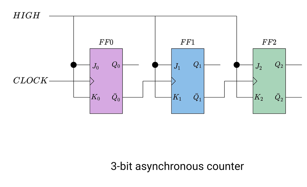
A 3-bit counter consists of three flip-flops and has 8 states. It can count from 000)2 to 111)2.
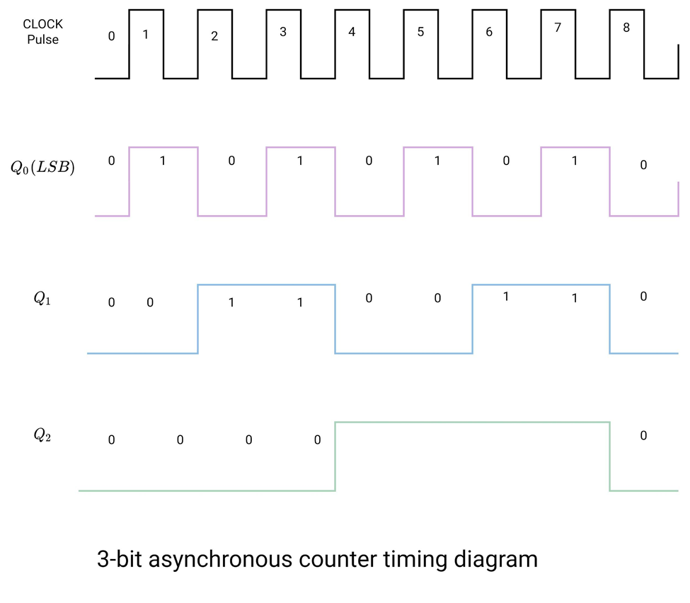
To observe the output of the counter, let’s apply 8 pulses to the CLK input of the first flip-flop (this is LSB) and observe the output at Q0, Q1 and Q2. Both J and K inputs are connected to logic HIGH. All flip-flops are positive edge triggered.
Initial condition:
Q0 = 0
Q1 = 0
Q2 = 0
CLK1:During the positive-going edge of CLK1 Q0 goes high and Q0‘ goes LOW. Q0‘ is connected to the CLK input of Q1 but it has no effect because a positive-going transition is required to trigger the flip-flop FF1.
Q0 = 1
Q1 = 0
Q2 = 0
CLK2:During the positive-going edge of CLK2 Q0 goes LOW and Q0‘ goes HIGH. This is the positive-going transition and the flip-flop FF1 is all set to trigger.
Q0 = 0
Q1 = 1
Q2 = 0
CLK3: This time Q0 goes HIGH again. Q0‘ goes LOW. It will not trigger FF1. So, FF1 remains in its state.
Q0 = 1
Q1 = 1
Q2 = 0
CLK4: This time Q0 goes LOW. Q0‘ goes HIGH. There is a transition that occurs in FF1. So, FF1 changes from 1 to 0. Q1‘ goes from 0 to 1 for the first time. This is a positive-going edge. Now FF2 is ready to change its state.
Q0 = 0
Q1 = 0
Q2 = 1
CLK5: Q0 goes HIGH. Q0‘ goes LOW. No changes occur in FF1 and FF2.
Q0 = 1
Q1 = 0
Q2 = 1
CLK6: Q0 goes LOW. Q0‘ goes HIGH. This time FF1 changes its state.
Q0 = 0
Q1 = 1
Q2 = 1
CLK7: Q0 goes HIGH. Q0‘ goes LOW. No changes occur in FF1 and FF2.
Q0 = 1
Q1 = 1
Q2 = 1
What will happen in the next clock pulse?
Q0 goes LOW. Q0‘ goes HIGH. This time FF1 changes its state from high to low. Q1‘ goes high. There is a positive-going edge for FF2. FF2 changes its state from high to low. All three flip-flops are reset to zero.
Q0 = 0
Q1 = 0
Q2 = 0
Synchronous Counters
These counters are made up of a series of flip flops, synchronized with the same clock signal. All of the flip-flops change their state simultaneously with a single clock pulse – at the same time. Synchronous counters work at a much higher frequency than their counterpart’s ripple counters, as there is no cumulative delay between the two flip-flops.
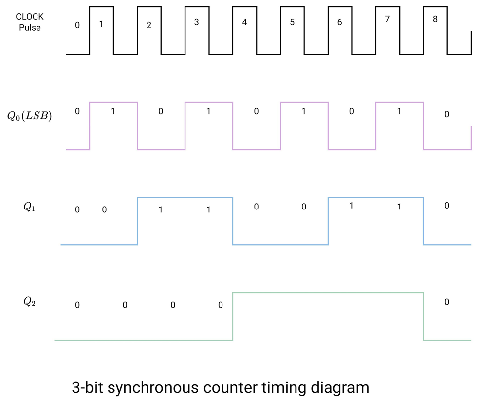
3-Bit Binary Counter:
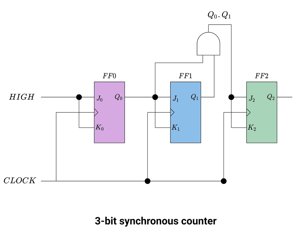
To observe the output of the counter let’s apply 8 clock pulses. Examine the waveforms at output Q0, Q1, and Q2. Assume all flip-flops are positive edge triggered.
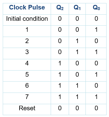
Initial condition
Assume that the counter is in a binary 0 state. And all flip-flops are RESET.
Q0 = 0
Q1 = 0
Q2 = 0
CLK1: When the positive edge of the first clock pulse appears, FF0 toggles. Q0 goes HIGH. Remember all flip-flops receive clock pulses at the same time. FF1 gets its J and K input from Q0. J1 and K1 inputs are low during CLK1 because Q0 has not gone high immediately. There is a propagation delay from triggering and propagating to the output Q0.
Q0 = 1
Q1 = 0
Q2 = 0
CLK2: When this clock pulse occurs, FF0 toggles and Q0 goes LOW. FF1 toggles its state and Q1 goes HIGH after some delay. Due to this propagation delay between clock pulse and output transition, FF2 remains in its initial state.
Q0 = 0
Q1 = 1
Q2 = 0
Delay
J1 = 1
K1 = 1
CLK3: When this clock pulse occurs, FFO toggles its state, and Q0 goes HIGH. FF1 remains in its previous state. FF2 remains LOW because there is an AND gate connected. When Q0 and Q1 outputs are HIGH, then the transition will occur in FF2.
Q0 = 1
Q1 = 1
Q2 = 0
Delay
J1 = 1
K1 = 1
J2 = 1
K2 = 1
CLK4: This time FF2 is ready to change its state. Q2 goes HIGH. FF0 toggles Q0 and goes LOW. FF1 toggles and goes LOW.
Q0 = 0
Q1 = 0
Q2 = 1
CLK5: During the positive-going edge of this clock, FF0 toggles, and Q0 goes HIGH. FF1 and FF2 remain in their previous state.
Q0 = 1
Q1 = 0
Q2 = 1
Delay
J1 = 1
K1 = 1
CLK6: During the positive-going edge of this clock, FF0 toggles, and Q0 goes LOW. FF1 toggles and Q1 goes HIGH. and FF2 remains in its previous state.
Q0 = 0
Q1 = 1
Q2 = 1
Delay
J1 = 0
K1 = 0
CLK7: During the positive-going edge of this clock, FF0 toggles, and Q0 goes HIGH. FF1 and FF2 remain in their previous state.
Q0 = 1
Q1 = 1
Q2 = 1
Delay
J1 = 1
K1 = 1
CLK8: When this clock pulse occurs, FF0 toggles Q0 goes LOW. FF1 toggles Q1 goes low as well. Q0 and Q1 are at the input of an AND gate. The output of the AND gate goes LOW as well. All the flip flops are RESET again.
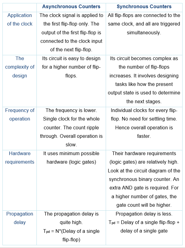
Difference Between Synchronous and Asynchronous Counters
The table below summarizes the difference between synchronous and asynchronous counters: