Introduction to Filter Circuits
15/06/2021, hardwarebee
In the first part of this guide, we presented the very basic concepts of circuit analysis: nodal and loop techniques, passive components and their equations, and the bipolar transistor. Now, you should be able to perform simple analysis in the time domain, predict the operation mode of circuit with diodes and calculate the bias point of simple amplifiers.
However, real-life circuits are difficult to solve in the time domain because the system will be composed by several differential equations. When non-linear components are added to the mix, the level of complexity becomes unpractical. In this context, the frequency-domain analysis was developed, using Laplace and Fourier transforms to solve the differential equations algebraically.
This guide will show the fundamentals of frequency analysis in a practical way, applying it on passive linear circuits. We will also discuss different filter circuits, that use the principles of frequency analysis in their design, such as low pass filter, high pass filter and band pass filter.
The Frequency Domain Analysis
Our brain is used to understand the world and the behavior of processes using time as reference. This is called “time-domain” analysis, and we are tempted to think about everything, including electronic circuits, with this framework. However, because differential equations are often not very intuitive and can be extremely difficult to solve, this approach is counter-productive for circuit analysis. Therefore, engineers and mathematicians developed the “frequency-domain” framework, using the Laplace transform.
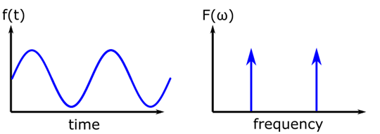
Figure 1: Time-Domain Analysis vs Frequency-Domain Analysis.
Laplace Transform
The Laplace transform is a mathematical tool that transforms a differential equation system into an algebraic system by converting the time independent variable ‘t’ into a complex frequency independent variable ‘s’. The solving steps consists of:
- Apply the transform to every equation of the nodal system.
- Solve the system in ‘s’.
- Apply the inverse Laplace transform to obtain the solution in the time-domain.
The equation below describes the Laplace transform, which is an integral transform:
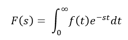
As you probably assumed, these transforms are complex and significantly difficult to obtain mathematically. However, the Laplace transform can be applied directly to individual components instead of the whole nodal equations, due to the linearity property. Because the equations describing electronic components are well-known, their Laplace transforms are readily available in the literature. Now, the solving process becomes a little different:
- Apply the Laplace transform to every component and signal of the circuit.
- Use the nodal or loop method to solve the system in ‘s’.
- Apply the inverse Laplace transform to obtain the solution in the time-domain.
Linear Components
The fundamental equation of each component can be transformed directly using Laplace. This results in a term representing the energy previously stored by the component and a term proportional to the ratio between voltage and current. The latter term is called impedance, which acts as a frequency dependent resistance.
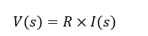
Resistor: as seen in the first tutorial, the resistor equation is constant in time:
![]()
Due to the Laplace transform properties, the transform of a constant function is simply the same constant. Therefore, the frequency representation of a resistor is the resistor itself.
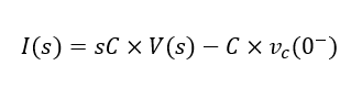
Capacitor: the capacitor equation, on the other hand, is defined by a time derivative of the voltage:
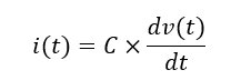
The Laplace transform of this equation is:
We can rewrite the equation in the following manner:
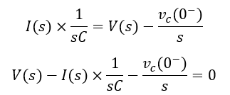
Notice that this equation respects the Kirchhoff Law of Voltage. Using this equation, we can find the circuit model of a capacitor in the frequency-domain. Figure 2 shows the frequency-domain model compared with the time-domain model.
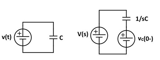
Figure 2: Frequency representation of a capacitor
The Vc(0-)/t term represents the voltage stored by the capacitor, and the 1/sC term is called capacitive impedance. The stored voltage term is a transitory signal that decreases exponentially to zero as the capacitor discharges. In stationary regime, only the impedance term matters, and the capacitor becomes equivalent to a ‘s’ dependent resistor with value 1/sC.
Inductor: similar to the capacitor, the inductor is defined by a time derivative of current:
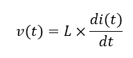
The Laplace transform of this equation is:
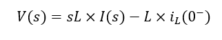
We can rewrite the equation:
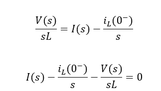
This equation respects the Kirchhoff Law of Currents, and thus is a nodal equation. We can represent the equivalent circuit of this equation as a current source I(s) , a parallel current source iL(0-)/s and a parallel impedance sL, as seen in Figure 3.
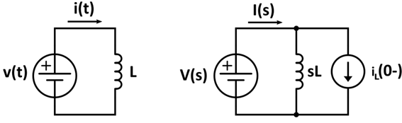
Figure 3: Frequency representation of an inductor
Similar to the capacitor case, the iL(0-)/s term is the stored current and sL is the inductive impedance. In stationary regime, the inductor acts like a ‘s’-dependent resistance, thus the name “impedance”.
Signals
Signal sources (voltages and currents) are also functions of time. Therefore, if the engineer is interested in the evolution of the signal, these elements should also be converted to the frequency domain when applying the Laplace transform.
- Sine: This is one of the most important signals in electronics. Not only because sines are easy to generate, but also because any signal can be described as a sum of sines. When transforming a sine wave, use the follow identity:
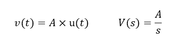
- Step: Step functions are also interested in electronics, especially to verify transitory aspects, such as rising time, overflow, settling time, etc.
Example
To better understand the method, let us solve a simple problem. Consider the circuit below, were we need to obtain the capacitor voltage VC:
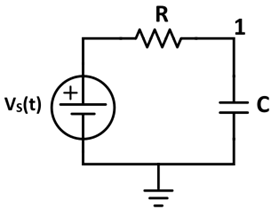
Figure 4: Step signal in series with a simple RC in the time-domain
Voltage VS is a step function with amplitude “VIN” and the capacitor is initially discharged. Now, we apply the Laplace transform, obtaining:
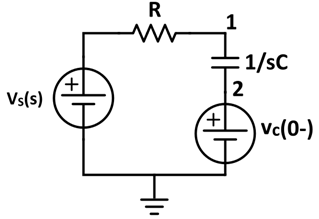
Figure 5: Step signal in series with a simple RC in the frequency-domain
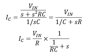
The capacitor current IC can be described as:
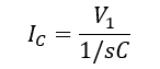
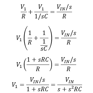
Therefore, we need to find V1. Because the capacitor was initially discharged, we can consider . The circuit can be solved applying nodal analysis to node 1. Using Kirchhoff’s Law of Currents, we obtain:
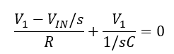
Now, isolating V1:
Now we can find the capacitor current:
Finally, we apply the inverse Laplace transform. Remember, the technical literature provides the transform and inverse transform of several functions that are important in electronic circuits, so we do not need to calculate the integral. Using the identity:
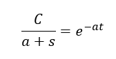
We can find the current IC in the time domain:
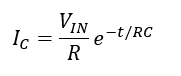
This result makes sense, because the current drops exponentially as the capacitor charges with the new voltage VIN. In t->infinity , the current drops to zero. Notice that the rate of the exponential factor is defined by RC. This parameter is called time constant, and describes how fast the signal changes in the circuit.
Filters
Although Laplace transform can be readily applied to find the signal in time, electronic analysis can, more often than not, be performed directly in the frequency-domain. That is: the inverse transform is usually not necessary. Frequency-domain analysis, also called small-signal analysis (for active circuits), can be performed in all linear circuits using the concept of transfer function. In these cases, we consider the circuit in stationary regime. Therefore, any previous charges and currents have been already dissipated, so we do not need to consider them.
Transfer Function Analysis
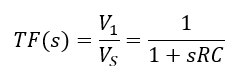
The transfer function (TF) is a function that fully describes the functioning of a linear circuit in the frequency domain. To obtain the TF, three things should be defined: the circuit structure, an input, and an output. The TF is basically the ratio between the input and the output for a given circuit. For instance, the transfer function of the circuit from Figure 5, considering the input VS and the output V1 is:
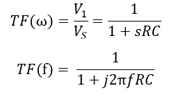
In a transfer function, ‘s’ can be replaced by ‘jω’, where ‘j’ is the imaginary unity and “ω” is the frequency of the input signal in rad/s. Typically we use frequency in Hz, which is f = ω/(2π).
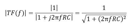
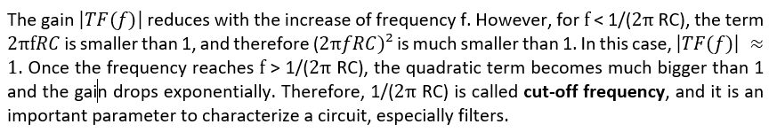
For a sine wave (and only for sine waves or constant signals), the TF(w) transfer function acts as a complex gain. The complex gain has a modulus and a phase: the modulus is directly multiplied by the input amplitude, whereas the phase shift is added to the input phase. In this tutorial, we are not going to discuss phase, for simplicity, but it is important to know that the TF introduces a phase shift. The gain modulus can be found using the following equation:
Low-Pass filter
Now we can finally discuss the main filter structures. The most common and useful filter type is the “Low-Pass Filter”, which is responsible for eliminating frequencies higher than a desired point. Two classical topologies of Low-Pass Filter (LPF) can be seen below:
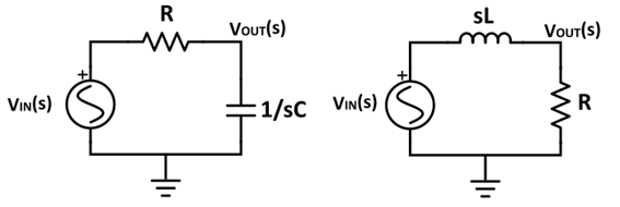
Figure 6: Low-pass filters using capacitors, resistors, and inductors
Considering the input and outputs, let us calculate LPF1(s)and LPF2(s) of both filters. Notice that we already transformed the components to their impedance form. Solving using simple nodal equations, and then replacing s with:
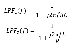
The gain modulus of both filters becomes:
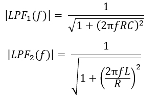
The cut-off frequencies are:
![]()
for the RC and the RL circuits, respectively. The gain vs frequency profile of the LPF can be seen below.
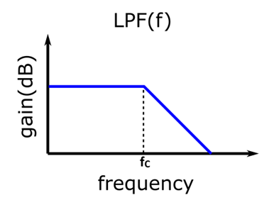
Figure 7: Low-Pass Filter Gain
For frequencies below the cut-off, the gain is approximately one, which is consistent with the idea that in DC the capacitor is an open-circuit, and the inductor is a short, as seen in Part 1. As the frequency increases from the cut-off, the gain drops exponentially.
High-Pass Filter
The high-pass filter is the opposite of the low-pass filter. Its job is to eliminate frequencies lower than the cut-off frequency. We can, usually, create a high-pass filter by switch the position of the circuit elements. For instance, switching the resistor and the capacitor from the Low-Pass filter of Figure 6, we have a High-Pass RC filter. The same occurs in the LR case, as shown below.
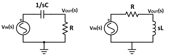
Figure 8: High-pass filters using capacitors, resistors, and inductors
Using exactly the same approach from the Low-Pass filter analysis, we can find the modulus of the high-pass filters (HPF) gain, described below:
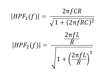
Notice that the denominator presents the same behavior as the Low-Pass Filter. However, now the numerator increases with frequency, and it is zero for DC signals. This means that, before the cut-off frequency (where the denominator is approximately 1), the numerator is growing with frequency, beginning from zero. After it reaches the cut-off, and
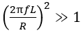
,the denominator can be simplified to
![]()
,which is the same as the numerator, thus bringing the gain modulus to 1. Therefore, the gain modulus of the high-pass filter is 1 for frequencies higher than the cut-off, and is less than one (eventually reaching zero) for frequencies smaller than the cut-off frequency. This behavior can be seen in the figure below:
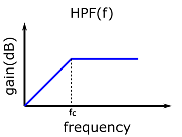
Figure 9: High-Pass Filter Gain
Band-Pass Filter
A band-pass filter (BPF) can be seen as the combination of a HPF and an LPF: it rejects frequencies below a lower cut-off frequency and after a higher cut-off frequency . The gain profile of such a
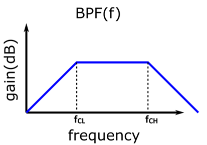
Figure 10: Band-Pass Filter Gain
The typical block-diagram of a band-pass circuit can be seen below. Circuit implementations can vary greatly, but an RC example is given besides the block-diagram. The design equations of and are the same ones given for the single LPF and HPF circuits.
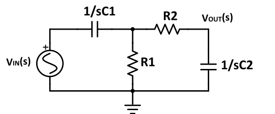
Figure 11: Band-Pass Filter Gain
Higher-Order Filters
The circuits given in this tutorial are called first-order filters. That is, the time derivative is of first order (which means that the ‘s’ variable exponent is 1). Higher-order filters can be made combining inductors and capacitors, or active devices, giving ‘s’ exponents bigger than 1 and better rejection capabilities. These filters will be discussed in future tutorials.