
Introduction to Power-on-Reset
12/05/2019, hardwarebee
A power-on-reset circuit is responsible for generating resetting signals whenever power is supplied to a given electrical device. In such manner, you can determine a known state in which the device always powers up or starts operating.
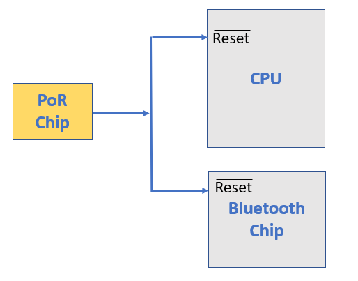
The risk in not having a power on reset signal is, for example, that your microprocessor will wake up with some random values in its registers and (address) counter, and therefore, the entire circuit will not operate properly. It is mandatory to ensure all digital circuits and chips are getting a reset signal when the supply voltage is stable after power up.
A modern power on reset circuity utilizes a timer. This onboard timer is only activated when the power supply achieves a predetermined voltage threshold beyond which the reset signal gets triggered and ensures that the system boots properly.
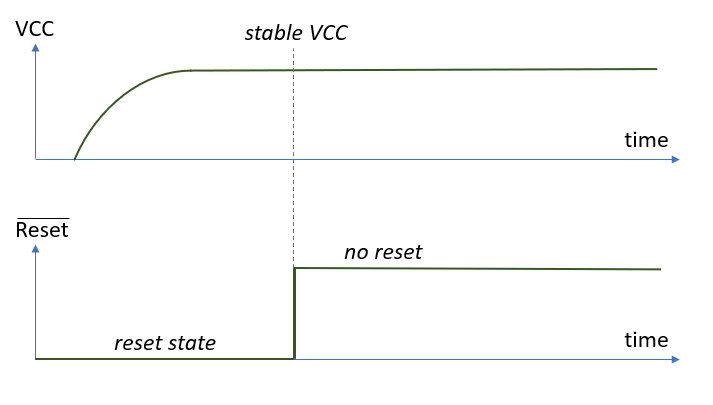
Considering the timer to expire after a specific period of time, resulting in the inactivation of the output of the power on reset circuit, leading to the activation of the device as the reset signal dies out. The device can now start operating. The power on reset signal prevents the CPU from running any software until a minimum level power voltage threshold is met and the clock is stable.
A power on reset circuit ensures the system power supply stabilizes at the correct levels, the clocks of the processors settle accurately, and that the loading of the internal registers is complete before the device actually starts working or gets powered up.
In analog power on reset implementation, the time and voltage threshold factors are characteristic of an analog circuit. The time period of the reset state is determined and measured using the charging of a capacitor which is placed in series with a resistor. When power is applied, the current goes via the capacitor and the voltage of capacitor increases slowly. At the beginning, the voltage is lower than the reset input pin threshold voltage and all elements in the CPU are hold in reset mode. And then, the voltage is higher than that threshold voltage, the reset pin gets a “1” and the system initializes. The values of the resistor and capacitor determine the power on reset latency.

A power on reset circuit also has good noise immunity which means that in the case that a power supply suffers a minor glitch that passes by quickly enough, it will not result in the production of a resetting signal as the microprocessor will be able to distinguish it from an actual trigger for the reset signal to be activated, unlike a voltage detector.
When designing a power on reset circuit, it is also important to ensure that it is only activated when the power source is consistent and constant for a considerable period of time so as to be able to assess the quality of the input power signal. It should also, ideally, be able to deactivate in the case that the power quality is poor.


