Digital System Design
18/06/2021, hardwarebee
The design flow to create new digital systems is a well-known process in the industry. However, beginner engineers may find it difficult to design complex digital systems, especially when involving systematic approaches and team-oriented organization, where simple ad hoc techniques are not effective. This article will discuss systematic digital system design, while as well showing basic concepts of digital systems, to simplify the process for those interest in the technology.
Analog vs Digital Systems
First of all, let us discuss the differences between analog signals and digital signals, so we can understand the advantages of digital systems that justifies its overwhelming use in today’s technology.
Analog Signals
The amplitude values of analog signals are continuously distributed on a range of voltages or currents. This means that the signal level can take any value. Also, the time distribution is also continuous, so there is information at any given point of time. Therefore, analog signals can provide information in a very straightforward way: for instance, the voltage value of a thermocouple can be directly related with the temperature, without any further codification. However, analog signals are difficult to process and to compute.
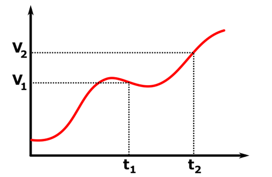
Figure 1: Analog Signal
Digital Signals
The amplitude of digital signals, on the other hand, are discretely distributed on a finite range of values. In modern systems, this amplitude is limited to only two levels, which corresponds to a logic 0 and 1. Also, time is discretized, which means that information can change only at integer multiples of a minimum time interval, called clock. This allows that all information contained in a signal can be accessed by doing only one measurement per clock.
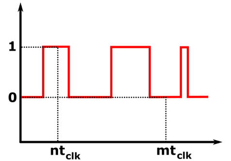
Figure 2: Digital Signal
Advantages of Digital Signals
In a sense, digital signals are also analog. The difference is how the information is stored. Because digital signals have only two levels, we can stablish a threshold of information: if the amplitude is above the threshold, it is considered a 1, and if it is below it is interpreted as a zero. This allows the application of Boolean logic, which is substantially easier than the calculus needed to process analog information. Therefore, using digital signals simplify the hardware and the computation process of systems.
Also, because the exact amplitude level is no longer important (only the comparison with the threshold), the signal is virtually immune to hardware degradation, such as external noise, temperature, aging, etc.
Therefore, digital signals are easier to design, can be programmed in different ways using the same hardware, are more economical, flexible, faster to process, easier to design, and can be scaled down to very small integrated circuits, populating a single chip with millions of logical gates.
Signal Compatibility
One of the most important parameters of a digital system is the logic level standard of the signal to be used. This is important because every component in a system should be compatible with each other, to ensure proper operation. There are five main standards in the industry: the 5 V TTL, the 5 V CMOS, the 3.3 V LVTTL, the 2.5 V CMOS and the 1.8 V CMOS.
Each standard defines the voltage amplitudes that defines the logical values of the signal. There are two specifications: the input logical levels (VIL, VIH) and the output logical levels (VOL, VOH). In a digital component, the input voltage is considered zero if below VIL, and one if above VIH. The same happens in the output, where voltages below VOL are considered zero and above VOH is considered one. Generally, VOH > VIH and VOL < VIL, to ensure that the output voltage from one component is correctly interpreted by the next component.
To understand compatibility, let us consider the case below, where a 2.5V CMOS circuit is cascaded with a 5V TTL circuit. The minimum output one for the 2.5V CMOS circuit is VOH = 2.3 V, which is higher than the minimum input one of the 5V TTL circuit. The same occurs with the logical zero, which is below VOL = 0.2 V for the CMOS output and VIL = 0.8 V for the TTL input. Therefore, the components are compatible in this configuration.

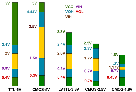
Figure 3: Voltage levels of several standards
Digital Design Paradigms
Digital systems are substantially less complex than analog systems. However, this does not mean that the design is easy in real-life. For small systems, engineers and hobbyists may achieve good results even using “on the fly” design approaches without systematic organization. However, for big systems, especially involving a team of professionals, it becomes unpractical to ignore good practices, hierarchical design techniques and systematic planning, documentation, and communication.
Ad Hoc Digital Design
Ad hoc design is usually the beginner’s approach for circuit design. It is basically the “design on the fly” paradigms, where problems are solved locally and isolated as they are found, without considering the device as a whole. Although this technique can work in simple circuits, it fails to manage complex systems, because the solutions designed for isolated problems often fail to yield the optimal behavior, systematically speaking. Also, this paradigm is really difficult to apply in team-based projects, as communication and compatibility between modules is unpractical.
Hierarchical Design
Hierarchical design consists in first observe the project as a whole, and then divide it into submodules. Each submodule is then designed separately, and treated as a “black box”. Now, each problem can be solved separately, however the interface between module should be designed in a standard, for compatibility and efficiency.
In team-based designs, each module can be designed by a different person or group. In this stage, communication is fundamental to avoid compatibility problems. Also, the I/Os of each module should follow previously stablished standards, which may vary from project to project.
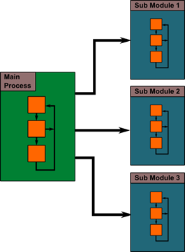
Figure 4: Hierarchical Design Block Diagram
Gajski-Kuhn Chart
The Gajski-Kuhn Chart, or Y-Chart, is a representation of hardware design levels and perspectives for a digital system. It is composed by five levels (represented by the circles) and three perspectives (represented by the arrows). Each circle describes a level of abstraction, and each arrow describes a way of viewing the circuit. The level of abstraction increases in the direction of the arrow.
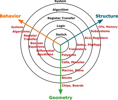
Figure 5: Gajski-Kuhn Chart
In the level context, circuit design can follow two approaches: the top-down approach and the bottom-up approach. The top-down starts the design from the higher level of abstraction (the system) to the lower level (the switch). The bottom-up approach is the opposite.
Top-Down: this method starts from the higher level of abstraction, the system circle. Basically, it starts with the definition of the system block, with its definition and description in terms of behavior, structure and/or geometry. Then, the block is divided into subsystems from the next layer of abstraction that are necessary to create the main block. The process continues until the design reaches the lower level blocks. This approach gives a more holistic view of the design, and it is easier to maintain coherence between modules and to keep in focus on the goal of the design, which is described in the main block.
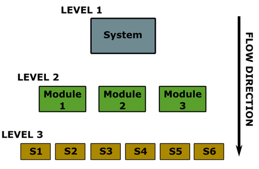
Figure 6: Top-Down Approach
Bottom-Up: this method, on the other hand, starts with the fundamental cells of the design, the submodules from the first level of abstract, the switches. The design is then performed from the lower to the higher levels of abstraction, finally reaching the main system block. This approach is more suitable for cases were the technology available to build the first blocks is limited, and the first blocks of the system should be designed first to avoid reaching specifications that cannot be satisfied by the available technology.
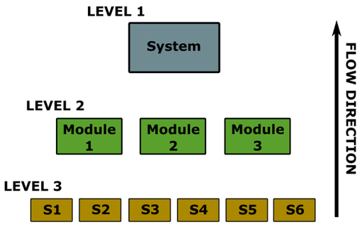
Figure 7: Bottom-Up Approach
Hybrid Approach: probably the most common method in the industry. The lower levels are defined by the semiconductor technology available, and thus they are designed using the bottom-up method. However, at the same time, the higher levels of abstraction are also designed using the top-down method. Finally, both design flows meet, completing the project.
Although there are three different perspective (Behaviour, Structure and Geometry), the design flow can switch between perspectives during the process. For instance, a top-down design can be begin at the behavior perspective in the system level, and jump to the structure perspective when reaching the register transfer level.
Digital System Design Steps
Problem Definition
The problem must be defined in a sentence or several sentences, to make the goal of the project clear to everyone in the team. For instance:
“Design a logical port that takes three inputs and delivers two outputs: Output 1 performs the AND operation between Input 1 and Input 2, and Output two performs the OR operation between Input 1 and Input 3.”
Functional Specification
Use logical statements to create a functional algorithm that describes the behavior of the system. In our simple example:
OUT1 = IN1 AND IN2
OUT2 = IN1 OR IN3
Block Diagram
Use block symbols to describe the signal flow, so each block is a different module of the whole system, and should be designed separately. The block diagram also specifies the relationship between every block.
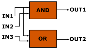
Figure 8: Block Diagram for the example digital system
Structural Design
Now each block should be designed and represented using the available technology. For instance, a microelectronic circuit can be used to design a block that is going to be manufactured directly on silicon, and Hardware Description Language can be used when a programable gate arrays (PGAs) are implemented. To simplify circuit representation, medium-scale integration (MSI) blocks, such as multiplexers and encoders.
Simulation and Testing
Finally, simulations can be performed on each block and in the whole system to validate the design. Several Electronic Design Automation (EDA) programs are available in the market for that. After simulating, the system can be manufactured and tested for real-world validation.


