
Inductors In Parallel
04/06/2022, hardwarebee
Inductors are said to be parallel if one or more inductors share the same two nodes. In this article we will discuss the topic around inductors in parallel and present the two common scenarios: with and without mutual inductance.
Inductors in Parallel – Background
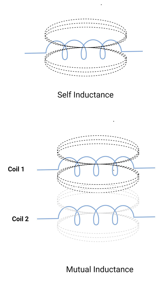
When a current flows through the coil, an electromagnetic field is created in its surroundings. When there is a change in current, the electromagnetic field also changes. The electromagnetic field surrounding a coil expands and collapses with an increase and decrease in current. It changes its direction with the current. This ability is called self-inductance. “When current flows through an inductor, it produces a voltage in the other nearby inductors.” This ability is called mutual inductance.
Consider two coils (coil 1 and coil 2 as shown in the figure below), if the current in coil 1 is increasing, it will create an increasing magnetic field around the coil. Similarly, the decrease in current will result in a decreasing magnetic field. This induces a voltage in coil 2 in an opposite direction to that of the current. In the same way, increasing and decreasing current will produce a similar magnetic field. The magnetic field generated in coil 2 will result in induced voltage in coil 1 (in opposite direction to that of the current). Similarly, if there are more than two coils connected in parallel, they will be linked together with the same magnetic field. If two or more coils are parallel to each other, such that changing magnetic flux lines cut through each other, they are said to have common mutual inductance, and it is denoted by M. It is measured in Henries (H).
How does it react to AC and DC?
The voltage across the inductor is zero when there is a constant current (that is DC) flowing through it. Or in other words, they act as a short circuit to DC.
The current flowing through an inductor cannot change abruptly or instantaneously. For a time-varying current, it opposes the change in current flowing through it. The voltage across the inductor can change abruptly.
Inductors in Parallel without Mutual Inductance
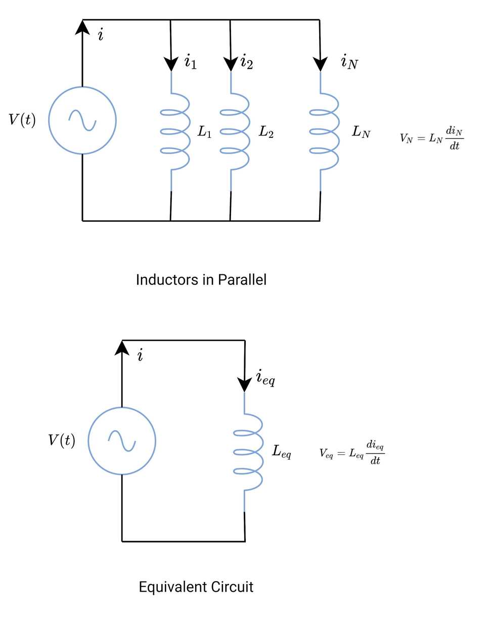
Inductors in parallel share the same two nodes. The voltage across each coil remains the same, whereas there are multiple paths for current to flow. See the figure below. There are ‘N’ parallel-connected inductors. The total current flowing through the inductor is given by Kirchhoff’s Current Law.
![]()
The current-voltage relationship of the inductors is given below.
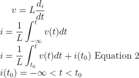
Substitute ‘i’ from equation 2 in equation 1; we get,
From the equivalent circuit, the initial current through Leq at t = t0 is the sum of inductor currents at t = t0.
![]()
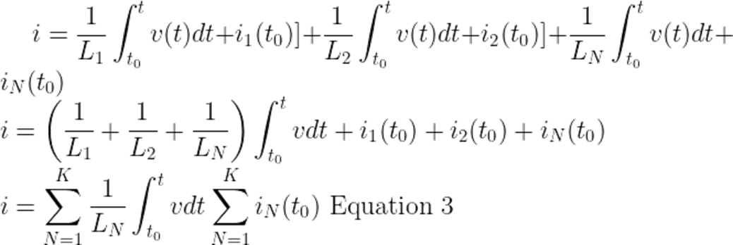
From the equivalent circuit, the inductor current equation is,
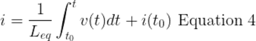
From equation 3 and equation 4
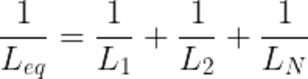
Where Leq is the equivalent inductance of the parallel-connected inductors.
In parallel-connected resistors, the reciprocal of the equivalent resistance is the sum of reciprocals of individual resistances. The same is true for parallel-connected inductors. The equivalent inductance is lesser than the smallest inductance in that connection. Or in other words, inductors in parallel decrease the effective inductance of the circuit.
When considering a resistive parallel circuit, most of the current flows through a less resistive path. It is true for inductive circuits as well.
The resistors are electrically connected. These coils are not only electrically connected as well as magnetically coupled. The above formula is only valid when no mutual inductance is present between inductors.
While working with inductive circuits, the electromagnetic forces should be taken into account.
Inductors in Parallel with Mutual Inductance
In parallel inductors, we cannot ignore the effect of mutual inductance.
If two coils are connected in parallel (with self-inductance L1 and L2) and are nearby such that the magnetic flux in one coil links with the other coil. Consequently, an EMF is induced in the other coil. Based on the EMF induced two types of connections are possible.
- Parallel aiding connection
- Parallel opposing connection
Have a look at the figure, magnetic field lines from both coils touch each other.
According to Faraday’s Law,
![]()
Where,
N = Number of turns
Φ = Flux
Any change in flux Φ, by the time-varying current, can be expressed as
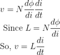
Where L is the self-inductance associated with each coil.
Each coil has its magnetic flux, which has two components. That is self-inductance and the other is mutual inductance.
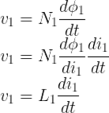
Let’s suppose Φ1 is the flux associated with coil 1. Assume that coil 2 carries no current.
![]()
Φ11 is the flux link coil 1 and the voltage induced is given by,
Φ12 links coil 2 and voltage induced is given by,
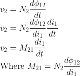
![]() is the open circuit induced voltage in coil 2. This voltage is induced because of the time-varying current in coil 1, which results in changing magnetic flux.
is the open circuit induced voltage in coil 2. This voltage is induced because of the time-varying current in coil 1, which results in changing magnetic flux.
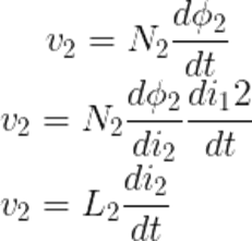
Repeat the same procedure for coil 2. Assume coil 1 carries no current. Φ2 is the flux associated with coil 2.
![]()
The induced voltage in coil 2 is given as,
The induced voltage in coil 1 because of Φ21
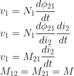
Mutual inductance is responsible for increasing and decreasing the inductance depending on the magnetic coupling between the two coils. The magnetic coupling, in turn, depends on the distance between two coils and their orientation to each other.
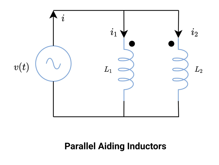
Parallel Aiding Inductors
In this type of connection, the EMF induced in both the coils are of the same polarity.
The total inductance is higher than the coils that do not have mutual inductance between them.
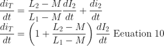
From KCL,
![]()
After differentiation,
![]()
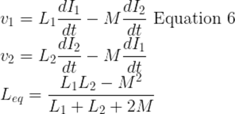
The total voltage across L1, that self-induced and mutually induced.
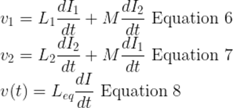
Since inductors and voltage sources are in parallel,
![]()
Compare equation 6 and equation 7
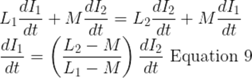
Substitute the di1/dt value of in equation 5 and eliminate it.
Equations 6, equation 7 and equation 8 are equal. Because of the parallel connection.
Compare equation 8 which is also equal to equations 6 and 7
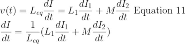
Substitute di1/dt from equation 9
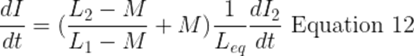
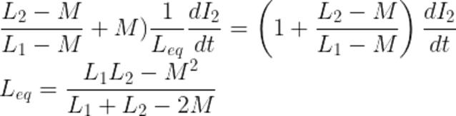
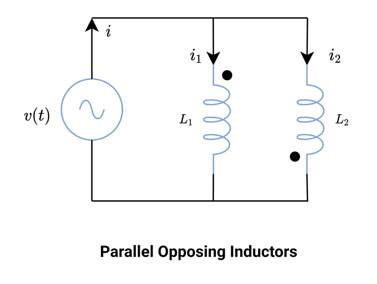
Parallel Opposing Inductors
In this type of connection, the EMF induced in both the coils are of the opposite polarity. The dot convention is used to show the connection is parallel opposing.
The whole derivation is similar to parallel aiding inductors. The only difference is induced voltage because mutual inductance is of opposite polarity. From equation 6 and equation 7, replace +M with -M.
Solved Example
Consider two coils, connected in parallel with each other.
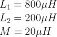
Calculate the effective inductance between two coils if two are connected in,
- Parallel aiding connection
- Parallel opposing connection
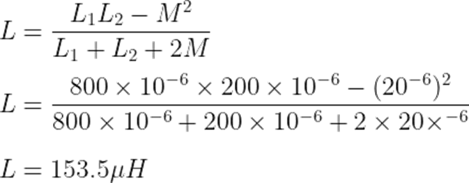
For parallel aiding:
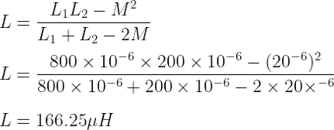
For parallel opposing:
Summary
From the above discussion, it is concluded that inductance diminishes on the parallel connection in the absence of mutual inductance.
![]()
Due to the presence of mutual inductance, the inductance calculated from the above-derived formula is invalid. There must be mutual inductance whenever two coils are placed in each other’s magnetic field. The mutual inductance may or may not decrease the total inductance.


