Understanding Half-Wave Rectifier
05/05/2022, hardwarebee
In this article, half-wave rectifier characteristics and applications are discussed comprehensively. In the beginning, the rectifier definition is explained, and then a half-wave rectifier circuit and its characteristics are presented. A rectifier is defined as a converter that converts an AC current to DC one. For this purpose, semiconductors must be used to rectify the current. Among all types of semiconductors, the diode is the simplest one which cannot be controlled by controllers. Other types of semiconductors are thyristors, MOSFETs, and so on. Generally, the rectifiers can be categorized as half-wave and full-wave rectifiers.
The diode is an uncontrolled semiconductor element that allows the current to flow in only one direction and prevents the current in the reverse direction. The diode is presented schematically in Figure 1. Most semiconductors are made of silicon, but germanium is also used for more accurate applications. This semiconductor device has two terminals, including an anode (positive) and a cathode (negative). When the anode voltage is greater than the cathode voltage, the diode is in forward bias and acts as a close switch. However, the diode is in inverse condition once the anode voltage is less than cathode one (open switch). Thus, there is no external control on diode operations except voltage level in the diode terminals.
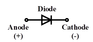
Figure 1: Diode terminals
The single-phase half-wave rectifier is the most basic and straightforward type of rectifier which needs only one semiconductor. In this article, a diode-based half-wave rectifier is introduced. As can be seen in Figure 2, a basic single-phase half-wave rectifier consists of an AC voltage source, a diode, and a load. In the left circuit, the diode allows half of the sinusoidal voltage and rejects the other half. It means that in the positive half cycle, the diode is in forward mode, and in the negative half cycle, the diode is in reverse mode. Inversely, the diode in the right circuit rejects the positive half cycle and passes the negative one. In this way, two single-phase half-wave rectifier configurations are built.

Figure 2: Single phase half wave rectifier configurations
As an example, the input and output waveforms of the left circuit are shown in Figure 3. In this figure, the input voltage is sinusoidal, and the output voltage shows the rectified input voltage. It can be seen that voltages are zero in the negative half-cycles, and they are the same as the input voltages in positive half cycles. The presented waveforms in Figure 3 are based on an ideal diode in the circuit, and the non-ideal diode is discussed later. In the positive half cycle, the anode voltage is greater than the cathode voltage, and the diode is in forward bias. Therefore, the input voltage is exactly transferred to the load. In contrast, the diode is in reverse mode in the negative half cycle, as the anode voltage is less than the cathode voltage, and the diode is off. It means that the circuit is open, and the load voltage is zero.
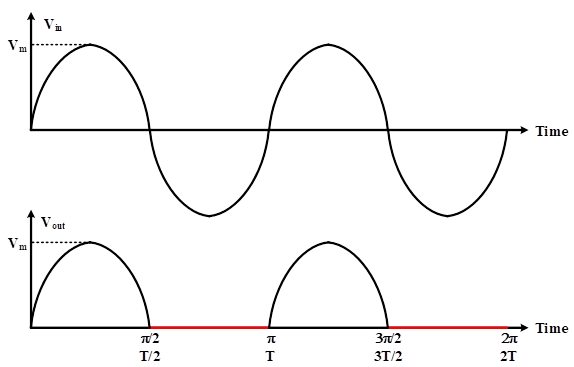
Figure 3: Input and output voltages of a sample single-phase half-wave rectifier
In reality, a silicon diode needs a voltage of more than 0.7V to be activated, and this value is 0.3V for germanium diodes. It means that the voltage difference between anode and cathode must be greater than 0.7 voltage to turn on the diode, and below 0.7V, the diode is off. Although this threshold is relatively low and can be neglected compared with the input voltage, the voltage drop should be considered for some purposes like loss calculations. In Figure 4, the diode is not ideal, and considering a 0.7V threshold is necessary for turning on the diode. Therefore, once the voltage goes higher than 0.7V in the positive half cycle, the switch is closed, and the input voltage is transferred to the load. Moreover, when the input voltage reaches less than 0.7V, the diode becomes off, and the load voltage would be zero. The negative half cycle is similar to the ideal diode circuit, and the load voltage is zero because the cathode voltage is lower than the anode one. The output peak voltage decreases with a non-ideal diode and would be equal to Vm-0.7 V.
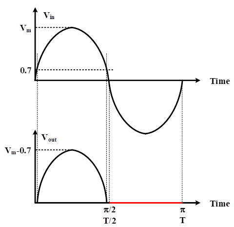
Figure 4: Input and output voltage of a sample single-phase half-wave rectifier with a non-ideal diode.
After the circuit explanation, some parameters should be defined to assess the converter performance. The first parameter is average load voltage. This parameter is also called DC output voltage and can be written as:
(1)

where Vm is peak voltage, t is time, is frequency, and T is the waveform period. In this situation, the average voltage can be calculated by:
(2)

The next parameter is the root mean square (RMS) value of the load voltage. To find the rms value, the below equation can be used:
(3)

For a resistive load, the peak output current can be calculated by using the following equation.
(4)

Average and RMS currents are similar to average and RMS voltages, respectively. Thus, the average current value is and the RMS current value is . Another parameter that is important in diode selection and sizing is peak inverse voltage (PIV). It defines as the maximum voltage that diode or other semiconductors can withstand before the breakdown in inverse bias. As can be seen in Figure 5, in inverse mode, the diode must tolerate the peak input voltage, and PIV would be equal to Vm.
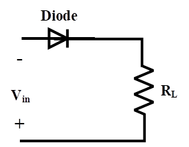
Figure 5: Diode inverse bias mode
The output voltage of a half-wave rectifier is called pulsating DC voltage, which has a ripple. Ripple is defined as a periodic variation of DC output voltage due to imperfection suppression of input AC voltage. Owing to the presence of ripple in rectifier output, a parameter is introduced, namely, ripple factor (RF). This parameter is the ratio of RMS current and DC current which is 1.21 for a single-phase half-wave rectifier.
(5)

The ripple factor of this type of rectifier is considerably high, and this undesirable value should be reduced. To decrease the value of ripple factor, a filter can be used in parallel with the load. This filter is a parallel capacitor which is shown in Figure 6.
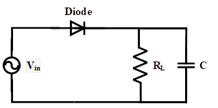
Figure 6: Single phase half wave rectifier with capacitive filter
At first, the capacitor is completely discharged, and the input voltage is zero. In the positive half cycle, the voltage goes up gradually to reach the peak input voltage. In this condition, the empty capacitor acts as a short-circuit path and becomes charged. The voltage of the charged capacitor is equal to the peak input voltage. By passing the peak voltage, the input voltage becomes less than the capacitor voltage (Vm). Therefore, the diode turns off, and the capacitor is discharged to the resistive load. Due to discharging of the capacitor, the output voltage decreases to reach the next positive half cycle. This process is repeated periodically, as shown in Figure 7. The output voltage is the red line in this figure, and its ripple is considerably low.
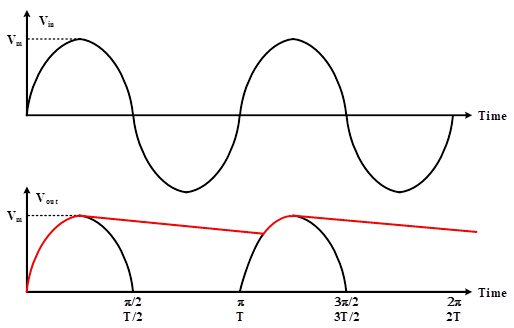
Figure 7: Input and output voltage of a sample single-phase half-wave rectifier with capacitive filter
For an effective operation of filter, the time constant of filter must be significantly greater than the input voltage period. It means:
(6)
RC >> T
where R is load resistance in ohm, C is the parallel capacitor in Farad, and T is the period of the waveform. This condition ensures that the discharge time is much greater than the charging time. In Figure 8, t1 is discharging time, and t2 is charging time. The longer discharging time, the lower the ripple presence in the rectifier output and better power quality.

Figure 8: Capacitor charging and discharging times
Using a filter is for reducing the ripple, but the ripple cannot be eliminated completely. Thus, ripple is available in the load voltage. The value of peak-to-peak ripple can be calculated based on the following equation.
(7)

where is output frequency of rectifier.
The last useful parameter in designing a rectifier is efficiency. This parameter presents how efficiently the AC input power is converted to DC power. According to the mentioned definition, efficiency is the ratio of output power and input power, and it is expressed as:
(8)

The single-phase half-wave rectifier is 40.6 percent which is relatively low and shows that only 40.6 percent of input power is converted to output power.
In most cases, the AC source is connected to the rectifier by a step-up or a step-down transformer to adjust the desired voltage for rectification. The modified half-wave rectifier is depicted in Figure 9. The transformer in this figure can be a step-up or a step-down transformer. When a transformer is used in a rectifier circuit, the transformer utilization factor (TUF) can be defined as the ratio of output DC power and the effective secondary power.
(9)

and secondary AC rated power can be obtained by:
(10)

This factor for a half-wave rectifier is 0.2865, which is considerably low. In other words, the secondary power must be around 3.5 times greater than the DC power output. Apart from that, DC saturation of transformer core in this type of rectifier is most probable, which produces high magnetizing current and core losses.
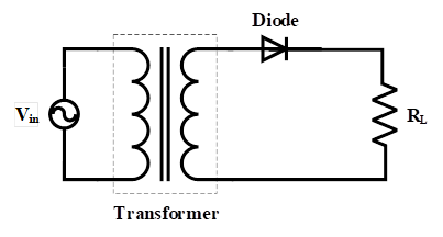
Figure 9: single phase half wave rectifier with a transformer to connect the source to the rectifier
The transformer utilization factor is a quantitative indication of the utilization of VA rating of the transformer. The more the value of TUF, the more will be the utilization. In other words, the VA rating of the required transformer will be less if TUF is more and vice versa.
All mentioned items express that the single-phase half-wave rectifier does not have acceptable performance and efficiency, but there are some advantages that satisfy designers to use it in their designs. This type of rectifier has a simple circuit and has a low cost because a few components are available in the circuit. Moreover, it is easy to use and easy to construct.


