
What is the Principle of an Electric Motor
27/05/2022, hardwarebee
Nowadays, electric motors can be found in everybody’s life because they convert electric energy to mechanical or kinetic energy. Eclectic motors are available in electric vehicles (EVs), fans, watches, mixers, grinders, washing machines, and many other apparatuses. Hence, knowing the motor principles can help everyone to use motor-based equipment more effectively. In this article, the principle of electric motor is discussed . Then, different common types of electric motors are presented, including DC motors, induction motors, and finally, the synchronous motors.
What is the Principle of Electric Motor
Electric motors work based on the magnetic field. The magnetic field can be produced by a magnet or windings around a magnetic core. To start the theory, the magnetic force of a current-carrying wire, which is exposed to a magnetic field, is explained. The magnet produces a magnetic field between N and S poles, as shown in Figure 1. The magnetic field lines exit from the N pole and enter the S pole. This magnetic field is constant, and there is no fluctuation in the magnetic field, which can be looks like a DC magnetic field.
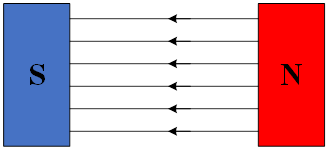
Figure 1: Magnetic field between N and S poles of a magnet
When a current-carrying wire enters the magnetic field, a magnetic force is applied to the wire, which makes the wire move. The amount of force depends on some parameters which are discussed in this article. The first parameter which impacts the magnetic force is the flowing current through the wire. If the current through the current is zero, there will be no force to the wire, and the force has a direct relationship with the current. Therefore, the following equation can be written.
(1)
![]()
where F is magnetic force, and I is the current in the wire. Another parameter is the length of wire that see the magnetic field. The relationship between magnetic force and exposed wire length is also direct, and it can be written as:
(2)
![]()
where l is the length of wire. The last parameter is magnetic field strength which has a direct relationship with magnetic force as:
(3)
![]()
These three parameters determine the maximum value of magnetic force, which happens when the magnetic field is perpendicular to the wire. Thus, any deviation from the perpendicular position reduces the amount of applied force to the wire. It means that the magnetic force in Figure 2 is not at its maximum value because of the angle between the magnetic field and the current in the conductor.
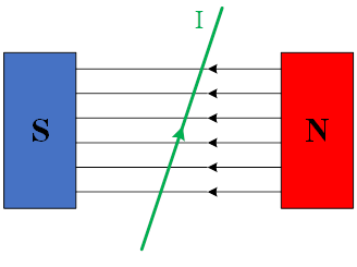
Figure 2: A current carrying conductor among a magnetic field produced by a magnet
Considering all parameters, the magnetic force can be calculated by given equation.
(4)
![]()
Now, instead of a single conductor, a loop can be considered between poles. The loop can be in any shape, but for better understanding, the loop is assumed to be in a rectangle, as shown in Figure 3. In this situation, each side of the loop carries a current and experiences a magnetic force. The force direction can be obtained by the left-hand rule.
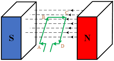
Figure 3: A close path of conductor in a magnetic field produced by a magnet
In this rule, the thumb is aligned with magnetic force, the forefinger shows the magnetic field, and middle figure presents the current direction, and all these fingers are perpendicular to each other. According to Equation 4, the magnetic force is zero when the carrying current is in parallel with the magnetic field. Thus, the magnetic force of BC and AD is zero. In this condition, only AB and CD experience magnetic force. By applying the left-hand rule to AB and CD paths, the magnetic force for the AB path would be upward, while for the CD path, the force direction would be downward. These two opposite forces rotate the loop, but it cannot complete its rotation because the current direction in the loop is constant. It means that the stable loop position is when the loop is perpendicular to the magnetic field. In this position, the upward and downward forces neutralize each other, and the wire loop cannot move. To solve this problem, the current direction in the loop must be revered in each half rotation to allow the wire loop to rotate. Moreover, the inertia will help the loop continue its rotation and pass the stable position.
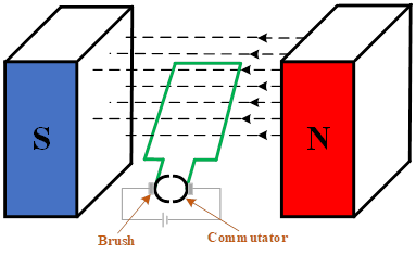
Figure 4: Commutator and brush for reversing the current direction in the loop
DC Motors
To achieve this goal, carbon brushes and commutators should be added to the circuit. As the battery wires cannot rotate together with the loop, two brushes act like a bridge to contact the loop to the battery. Furthermore, the commutators change the current direction in the loop when the loop rotates in the magnetic field. These principles are for the DC motor as a DC source is connected to the rotational part of the motor. Motors commonly have a static part called a stator and a moving part, namely a rotor. Both parts are made of a magnetic core and windings. In a DC motor, a magnet is used in the stator part. However, the constant magnetic field can be produced by wrapping wires around the stator and connecting the terminals to a DC voltage source. Moreover, many wire loops are connected to the commutators to increase strength and help the motor rotate faster. In DC motors, the airgap between stator and rotor is uniform.
AC Motors
The theory behind the AC motor is the same. It means that a magnetic field is necessary, and the rotor windings are forced to rotate. However, in AC motors, the stator windings are connected to an AC voltage source, and magnets cannot be used for stators as the magnetic field produced by the magnet is constant. AC motors are categorized into two main groups, including induction motors and synchronous motors, which will be discussed in the following parts. Most of the motors in the industry are three-phase induction motors which are used in fans, pumps, and so on. However, single-phase induction motors are used in home appliances, like refrigerators, mixers, and so forth.
In induction motors, the airgap is not uniform, the stator core is laminated due to eddy losses, and it has slots cut on the outer surface. The three-phase windings are inserted in the stator slots to generate AC magnetic field in the airgap. There are two types of a rotor winding which are called squirrel-cage and wound-rotor types. In induction motors, there are no current-carrying windings because the AC rotational magnetic field changes with time and its variation force the rotor windings to rotate in the direction of the magnetic field. The AC magnetic field generated by stator windings rotates in the airgap with synchronous speed, but the rotor speed is less than the field speed in an induction motor.
Unlike the induction motor, the synchronous motor can rotate at a constant speed in the steady-state condition. Hence, synchronous motors can be used where a constant speed is critical such as electric clocks, timers, or many on a large scale can be used as pumps. However, synchronous machines are used as a generator rather than a motor. In powerplants, there are many synchronous generators, but synchronous motors have limited applications. The stator structure of the synchronous motor is similar to the induction motors, but the rotor winding carries a DC current.
Motor Applications
Electric motors are used in many industries. For instance, electric trains work with DC motors and induction motors. Moreover, different types of motors are used in electric vehicles. In the past, DC series motors were widely used for this purpose. These days brushless DC motor (BLDC) or Permanent Magnet Synchronous Motor (PMSM) are used together with induction motors. Motors are even used in household appliances, like grinders, mixers, blenders, electric toothbrushes, etc. Other common applications are compressors, ships, and elevators. In the following section, Tesla EV motors are presented comprehensively.
Tesla Car Motors Overview
Tesla as a pioneer in EVs, uses different types of electric motors to achieve higher efficiency and address the users’ needs. Induction motors are mostly used in EVs, but Tesla introduces a new motor for its new models. The induction motor principles have been defined in this article which there is a squirrel-cage rotor and a stator connected to the AC voltage source. As the main source of energy in EVs is batteries, the battery DC voltage is converted to AC voltage to feed the induction motor. The induction motors are efficient, but three to four percent of energy is lost in the rotor bars for a long drive at cruise speed. Another parameter is starting torque which must be enhanced in EVs. Hence, the motor should be improved based on this need. The squirrel-cage rotor can be replaced by a permanent magnet around the solid iron cylinder to generate a constant magnetic field in the airgap. This construction removes the rotor loss in the previous motors because there is no induced current required, which increases the motor efficiency, and additionally, it has better starting torque compared with the induction motor. Moreover, the PM rotor works like a synchronous motor because of the constant magnetic field, which enables the motor to rotate at a synchronous speed. However, PM motors have some limitations. They cannot work at high speed because the permanent magnet produces back-EMF in stator windings and reduces its performance considerably. Furthermore, strong magnets will result in magnetic eddy current losses that increase the heat in the motor. For better performance, synchronous reluctance motors can be used in EVs. In this type of motor, some slots are created inside the rotor. As the rotor tends to a low reluctance, it keeps its low reluctance position and rotates with the magnetic field. This construction is acceptable for high-speed applications and has no back-EMF. The newest type of motor that Tesla uses in its EVs is a combination of PM and reluctance motors by placing PM in the reluctance motor slots. In this way, the motor can work effectively at any speed.


