Zener Diode Is Used As
01/06/2022, hardwarebee
Zener diode is considered a special purpose diode because it can operate in a reverse biased mode. Because of this, these diodes are used in voltage regulation and waveform shaping circuits. In this tutorial, two types of voltage regulation circuits with Zener diodes are discussed. In addition to voltage regulators, the other application is waveform shaping where a Zener diode is used as a clipping element.
Zener Diode Used as a Voltage Regulator
Zener diode is mostly used in voltage regulator circuits — operating in the breakdown region can keep nearly a constant voltage across its terminal over a specified range of reverse current values. This ability makes it suitable to work as a voltage regulator and keeps a reverse voltage constant.
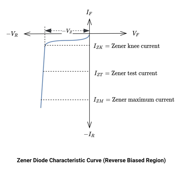
From the characteristic curve, IZK is the minimum reverse current that keeps the diode in the Zener breakdown region. Below this value, the Zener won’t be able to work as a voltage regulator. Between the current values of IZK and IZM, the curve is almost a straight line. This is the breakdown region or Zener voltage Vz. In this region, the internal diode resistance decreases rapidly, and hence the reverse current increases. VZ is almost constant ideally, but there is a slight increase as the diode current increases. IZM is the maximum reverse current, beyond this value, there is an avalanche breakdown region. Between IZK and IZM the Zener voltage (VZ) remains constant. For a particular diode, VZ, IZK, ZZ, IZT and IZM are stated in datasheets.
These diodes are used as a voltage reference element in sensitive circuits. As a result, it has a controlled reverse-biased property, which is constant over temperature and time.
In this tutorial, two types of Zener based voltage regulators are discussed.
- Regulation with variable input voltage
- Regulation with variable load
Regulation with Variable Input Voltage
The circuit below shows a Zener diode with an input voltage source and a resistor which is a current limiting resistor.
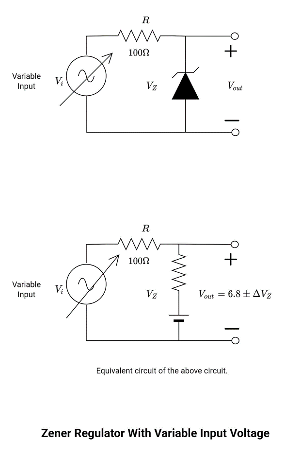
In the figure, the diode is driven by a voltage source which may vary within certain limits. The input voltage (Vi) may vary in a suitable range to ensure that the diode remains in its ON state. As the input voltage increases, the current flowing through the circuit increases and vice versa. Similarly, the change in input voltage and current leads to change (increase and decrease) in diode current and voltage. Keep in mind that the load resistor remains the same as well as the current flowing through the load.
For fixed values of the load resistor, the minimum input voltage (Vi(min)) is fairly larger than the nominal diode voltage (VZ). The maximum input voltage is determined by the maximum Zener current (IZM). Assume ZZ is constant from IZK to IZM.
![]()
The minimum input voltage value is determined by the Zener current (IZK).
![]()
To determine VZ, using the simplified model of the diode.
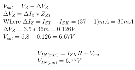
Vout varies slightly because of internal resistance. Vout at IZK is calculated as follows:
![]()
![]()
Vout at IZM is calculated as follows:
![]()
The maximum value of input voltage is determined by the maximum value of Zener current (IZM).
![]()
Example: Determine minimum and a maximum output voltage that can be regulated with a 1N4736 diode.
Nominal Zener voltage VZ = 6.8V
Zener test current IZT = 37mA
Zener impedance ZZT =3.5 Ω
Zener knee current IZK = 1mA
As is already explained, the diode voltage in the breakdown region varies slightly because of the internal resistance. This is ∆VZ.
VIN(max) occurs at maximum Zener current, that is IZM.
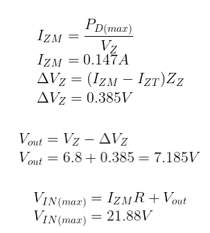
The minimum input voltage is 6.77V and the maximum allowable voltage is 21.88V. In this circuit, the diode works as a regulator if the input voltage varies between these voltage values.
Regulation with Variable Load
The circuit below shows a Zener diode with an input voltage source and a resistor which is a current limiting resistor. The circuit is the same as the previous circuit where Zener diode is used as limiting element. Here, the load resistor may vary but of course, the voltage across it remains the same because of the diode.
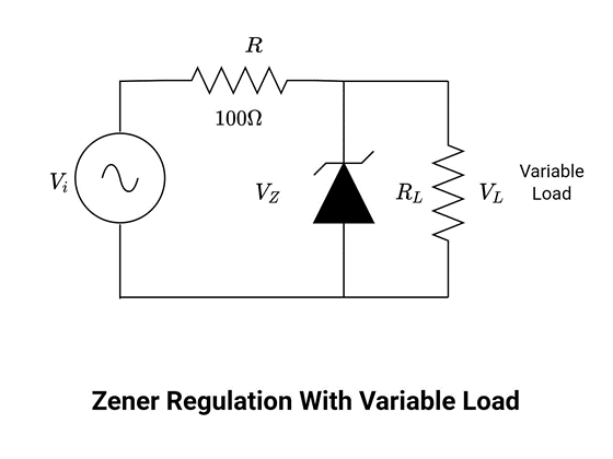
In the figure above, the diode is driven by a fixed voltage source but the load resistor is variable. The load resistor (RL) may vary in a suitable range to ensure that the diode remains in its ON state. These regulators can maintain a constant voltage across the specific ranges of a load resistor (and hence load current). A too-small resistor will result in small voltage across the load (VL) and hence across the diode.
![]()
When a load resistor is connected, total current divides and flows through Zener (IZ) and the load resistor (IL). If RL decreases IL increases and IZ decreases. However, the input current (IT) remains the same and the Zener voltage (and hence the voltage across the load) will become constant, once IZ reaches IZK. At this point, the diode is in the ON state and starts working as a voltage regulator and maintains its voltage over the range of current values (that is from IZK to IZM).
![]()
Example: Determine minimum and maximum load current for which the diode will maintain regulation. Calculate minimum RL.
The maximum current will pass through the diode if the load resistor is of infinite value. Suppose the RL is infinite and the current flowing through it is approximately zero. In this case, maximum current will flow through the diode. Calculate it
So, it can handle this current without being damaged.
The other condition is when the minimum current will flow through the diode. But the minimum current should be greater than IZK, to ensure that the diode remains in the ON state. Whereas the load current is going to be maximum. Keep in mind the input voltage and current remains the same. In this case,
![]()
Calculate the maximum current through the load. When the current is maximum, the resistance is minimal. Calculate the minimum value of RL.
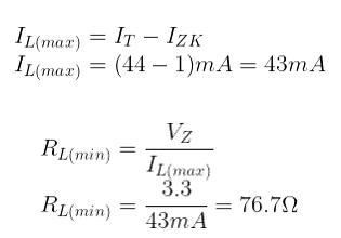
The possible values of RL = 76.7Ω to infinity. This value maintains the voltage regulation. If RL(min) is less than 76.7Ω, in this case, more current will start flowing through RL, and it will drop diode current from IZK (the minimum current to turn on the diode). And voltage regulation will not be established.
Zener Diode Used As a Waveform Clipper
The major application of these diodes is as a voltage regulator – e.g. Zener diode is mostly used in voltage regulator circuits. But they can also be used for waveform shopping or clipping purposes as well. These circuits are also called diode limiters. In these circuits, the Zener diode is used as a limiter.
According to the schematic diagram shown below, it can work as a positive peak clipper or a negative peak clipper or clips both peaks to selected Zener voltage.
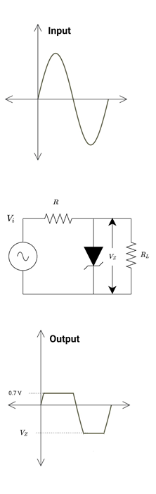
Zener Diode Used as a Negative Peak Clipper
The circuit below clips the negative half cycle and sets the positive peak to the Zener diode VZ level.
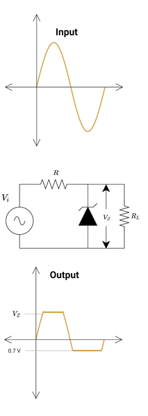
During the positive half cycle, the diode is reverse biased until input voltage is less than Zener voltage (Vi<VZ). And hence input voltage appears across the output. When the input voltage is greater than the input voltage (Vi>VZ), the diode starts conducting in reverse biased mode, and hence the current starts flowing through the diode. The output waveform is set to VZ.
During the negative half cycle, the diode starts conducting at 0.7 V. The current starts flowing through the diode and the output waveform clips after 0.7 V.
Zener Diode as a Positive Peak Clipper
There is another circuit, the diode is connected in the opposite direction. It clips the positive peak and sets the negative peak to the Zener voltage level. The working of both circuits remains the same as discussed earlier.
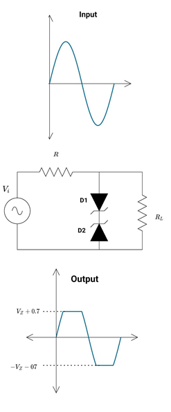
Double Zener as a Diode Clipper
In this circuit, the sinusoidal waveform becomes the square wave after clipping through the diode. For a better square wave, the amplitude of the input signal should be large enough. In these types of circuits, one diode behaves as a limiter while the other diode behaves as a simple forward-biased diode
During the positive half cycle of the input voltage, D1 is forward biased at 0.7 V. While D2 is reversed biased until input voltage is greater than Zener reverse voltage (for D2) and forward diode voltage (for D1). Here D1 works as a limiter diode while D2 is a simple forward-biased diode. Input voltage appears across output until Vi = (VZ + 0.7) V and then clips.
Similarly, during the negative half cycle of the input voltage, D1 works as a Zener limiter, while diode D2 is a simple forward-biased diode.