
The Ultimate Guide to Analog Sensors
28/05/2023, hardwarebee
Introduction
An analog sensor is a type of sensor that measures physical quantities or environmental conditions and provides an output signal in analog form. Analog signals are continuous and can vary across a range of values, as opposed to digital signals that are discrete and represented by binary values (0s and 1s).
Analog sensors detect and convert physical phenomena, such as temperature, pressure, light intensity, or sound, into proportional electrical signals. These sensors typically utilize various principles, including resistance, capacitance, inductance, or voltage, to measure and represent the input variables.
The output of an analog sensor is typically a voltage or current signal that changes in direct proportion to the input being measured. For example, a temperature sensor may output a voltage signal that corresponds to the temperature being sensed. The relationship between the measured quantity and the output signal is often linear, although in some cases, it can be nonlinear and require additional calibration or conversion.
Analog sensors are commonly used in numerous applications, including industrial control systems, environmental monitoring, medical devices, scientific research, and many others. The analog signals generated by these sensors can be further processed, amplified, or converted to digital form using analog-to-digital converters (ADCs) to interface with digital systems for further analysis, display, or storage.
A sensor is a device that senses or measures physical quantities and produces an output proportional to the measurement. The physical quantities could include level, flow, humidity, temperature, pressure, speed, and more. There are various types of physical quantities, and hence several sensors are available that detect changes in physical quantities.
Sensors are classified into so many types and categories. This article will cover analog sensors.
How do Analog Sensors Work?
A sensing unit can be a simple sensor or some additional components. If a sensing device works with a microcontroller, the following blocks are required.
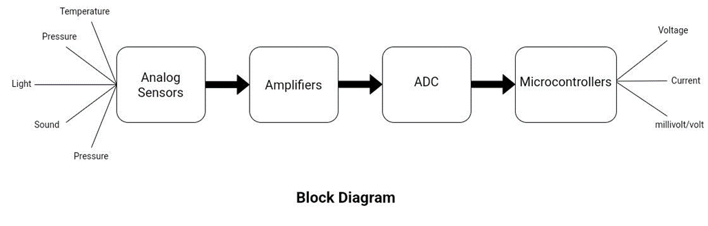
To utilize the small output generated by sensors, a system is employed comprising multiple blocks such as amplifiers, ADCs, etc. Analog sensors produce continuous or analog signals. The output signal from these sensors needs to be connected to other electronic devices. Since sensor outputs are typically small (in fractions of a volt), an amplifier is necessary to convert the output into a usable form. The amplified signal is then passed through an analog-to-digital converter (ADC) to digitize the output, which can then be processed by a microcontroller.
Sensors Versus Transducers
These are the two terms that are used interchangeably. But there is a difference between them. A sensor is a device that detects and responds to changes in physical parameters such as temperature, light, speed, and pressure. It converts these changes into electrical signals. On the other hand, a transducer is a device that converts one form of energy or physical quality into another. While all transducers are sensors, not all sensors can be considered transducers.
Types of Analog Sensors
Some of the most common analog sensors are listed below:
- Accelerometers
- Pressure sensors
- Light sensors
- Sound sensors
- Temperature sensors
Accelerometers
Accelerometers are used to measure acceleration forces (the force caused by a change in an object’s motion, position, or vibration). There are two types of acceleration forces, static and dynamic. An example of static acceleration is the force of gravity, which is constantly acting on the earth’s surface. These types of forces help to detect the orientation of the device. Static accelerations are predictable and uniform to a large extent. On the other hand, the dynamic acceleration is unpredictable and non-uniform and it is caused by the movement of the device. Therefore, dynamic acceleration allows the sensor to detect the motion and change in velocity (acceleration) of the device.
Working Principle
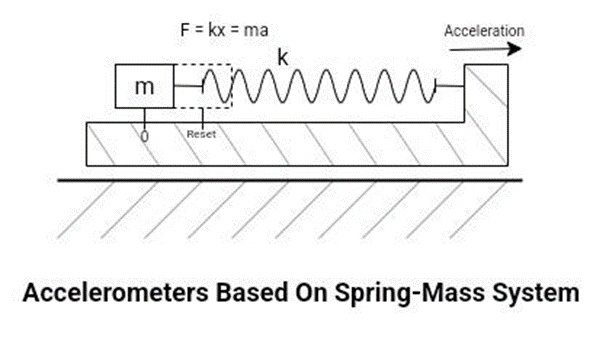
Accelerometers are used to measure the displacement of an object. Many accelerometers use a spring-mass system to measure acceleration. The basic physical principle behind these accelerometers is known as Hooke’s Law. Which states that, “The force needed to extend or compress a spring by some distance is proportional to that distance.”
F=kx
Where k is the constant of proportionality between F (force) and x (displacement).
Acceleration is produced when the force is applied to the spring-mass system. According to Newton’s second law of motion,
F = ma
F = ma = kx
If the force ‘F’ is applied, an acceleration is produced and the mass is displaced. If we observe the displacement x, then the acceleration is given as,
a = kx/m
If we observe the acceleration, then the displacement is given as
x = ma/k
Application
- Commonly found in smartphones and digital cameras. It is responsible for adjusting the display (landscape or portrait) based on the orientation.
- Accelerometers are crucial to the functionality of fitness trackers and are used to monitor a variety of metrics related to exercise and physical activity, including steps taken, distance traveled, and calories burned.
- In industries and power plants, where machines are in continuous motion, they may generate vibrations. These vibrations can be harmful to the machines. These sensors are responsible for detecting unwanted vibrations.
- These are also helpful in detecting the orientation of heavy machines in the industry.
- Controlling the stability of drones, aircraft, and spacecraft.
- Vehicles often rely on accelerometers for a variety of purposes, including tire pressure monitoring, suspension systems, engine management systems, and tracking the vehicle’s acceleration and deceleration.
Pressure Sensors
Pressure sensors are devices that sense and measure the pressure of gases or liquids. It is an electronic measuring device for detecting, controlling, reading, displaying, and keeping track of various changes in the applied pressure. It then interprets physical data into an electronic signal. Pressure is defined as the amount of force exerted on a unit area.
P=F/A
There are various ways to categorize them. Pressure sensing devices work on diverse electrical principles and hence have many different types like strain gauge, capacitive, piezoelectric, piezoresistive, optical, resonant, and thermal pressure sensors. Each of them has unique application requirements.
Working Principle
This article gives an overview of commonly used strain gauge pressure sensors. There are four strain gauges along with sensing elements (diaphragm). The strain gauge is made up of a special conductive material known as piezoresistive material. Its resistance varies as the applied pressure changes.
The strain gauges are connected in a Wheatstone bridge configuration. The diaphragm expands and contracts as pressure is applied or relieved. These strain gauges measure these physical deformations and convert them into an electrical signal.
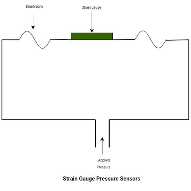
The output of the bridge is ∆V, proportional to the applied strain or force F. The resistance of a conductor is directly proportional to its length and inversely proportional to its cross-sectional area. So, as the pressure applies, the diaphragm stretches (and hence the length increases, while the cross-sectional area decreases), and the resistance increases at the same time. The change in resistance is proportional to the pressure applied.
Applications
- They are commonly found in vehicles to detect tire pressure, engine oil pressure, and fuel pressure.
- They are commonly found in biomedical devices like blood pressure monitors and high-pressure inflation devices.
- They are commonly found in aircraft. Pressure sensors are responsible for measuring atmospheric pressure, altitude, and fuel pressure on aircraft.
- In industrial processes, they help measure the pressure of fluids or gasses in pipes and vessels, detecting leakage and malfunctions.
Light Sensors | Photodetectors | Photo Sensors
Photodetectors are optoelectronic devices that convert light or any other form of electromagnetic radiation into an electrical signal. Mostly, these are used for detecting electromagnetic radiation in visible regions. There are sensors available that are capable of detecting (photons) frequencies ranging from infrared to ultraviolet. There are many different ways to implement photosensors. All light sensors operate according to one of the following principles.
Photoconductivity: These photos sensors change their conducting properties when exposed to light. They are commonly found in photodiodes. Photodiodes work on both photoconductive and photoelectric effects. Some common sensors based on photoconductive effect are:
- Photodiodes
- Phototransistors
- LDRs
- Photocells
- Photoconductive semiconductor switches
Photovoltaic effect: The photo sensors based on the photovoltaic effect are extensively used in solar energy systems.
Photoelectric effect: There is a wide range of sensors available that work on photovoltaic effects. These are commonly found in imaging devices, electric eye (automatic door sensing unit), spectroscopy, barcode scanner, etc. Some common sensors based on the photoelectric effect are:
- Photodiodes
- Photomultipliers
- Phototubes
- Image intensifiers
The choice of the principle used depends on the specific application requirements, such as the desired sensitivity, speed, and spectral range.
Working Principle
The predominant type of photodetectors is known as photodiodes. They are the simplest and most common type of photosensor. They work on photoelectric effects. They are made up of semiconductor materials, smaller in size, and the detection efficiency is quite high. They are diodes, so made up of p-n junctions or p-i-n junctions (PIN junctions), where ‘i’ is the intrinsic (undoped) layer sandwiched between p-type and n-type semiconductors. This layer enhances the photodetection capability of the diode.
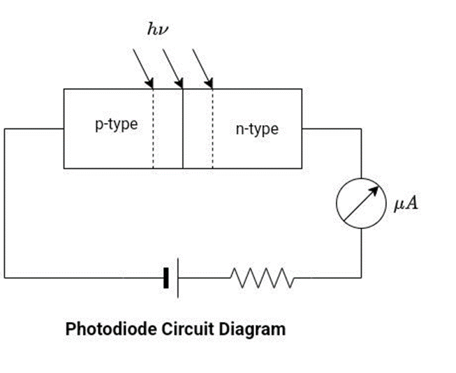
When they are exposed to light and photons of sufficient energy (h𝛎 greater than band gap energy Eg) strike the light-sensitive surface of the diode, carriers are excited and EHP (electron-Hole Pair) is created. The photocurrent, or light-generated current, is directly proportional to the intensity of the light. This current flows in the opposite direction from the normal rectifier diode. Because they are designed to work in reverse-biased mode. This reverse current is known as photocurrent. The magnitude of photocurrent depends on the intensity of light. Have a look at the schematic diagram, the photodiode is connected in reverse biased configuration.
Applications
- Photodetectors are the key components of optical communication systems. It has a great impact on the overall performance of these systems.
- Light-sensing cells that use photovoltaic effects are known as photovoltaic cells or solar cells. These cells are used as building blocks for solar panels.
- Remote control devices require photodiodes for conducting their function.
Sound Sensors
They are used to detect sound signals (which are in the form of vibrations) and convert them into output signals. It is simple, easy to use, and cost-effective.
Working Principle
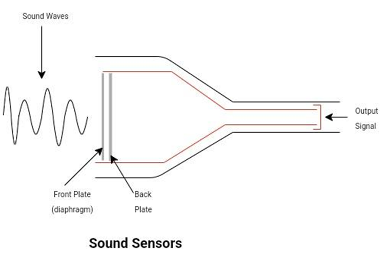
The working principle of sound sensors is easy and similar to that of our ears. Within the ear, a diaphragm is present to detect sound waves and convert them into signals. This article will discuss sound sensors with electric condenser microphones.
- These microphones consist of a parallel plate capacitor. One of the plates is fixed, known as the back plate, while the other plate is movable, known as the diaphragm.
- When the sound signal falls on the diaphragm (the front plate of the capacitor), it starts to vibrate, causing a change in the distance between the two plates.
- The movement of the diaphragm and the change in distance between the two plates result in an electric signal that is captured by the microphone.
- The value of the signal corresponds to the intensity of the sound, meaning that it increases as the sound becomes louder.
Applications
- They are commonly found in all types of sound recording systems.
- Sound sensors play a crucial role in many seismological instruments (instruments that use to detect and measure the motion of the ground during an earthquake).
- They are commonly found in ultrasound imaging devices.
Temperature Sensors
Temperature sensors sense the hotness and coldness of objects and give results in the form of electric signals. They are commonly used in sensing temperatures in solids, liquids, and gases. These are the most commonly used sensors in homes. Like, water heaters, irons, thermometers, heating and cooling systems in homes, etc. There are several different types of temperature sensors available, and each of them has its own area of application.
They can be broadly categorized based on the mode of connection as follows.
- Contact type: To obtain a reading, the sensor probes must be in contact with the object whose temperatures are being recorded.
- Thermistors
- RTD
- Thermocouple
- Thermostat
- Non-contact type
- Infrared sensors
- Optical pyrometer
Working Principle
Thermocouples are commonly used electronic temperature-sensing devices that operate based on the Seebeck effect. They have the widest range of temperature operating ranges, are simple, inexpensive, have a quick response time, and are reliable.
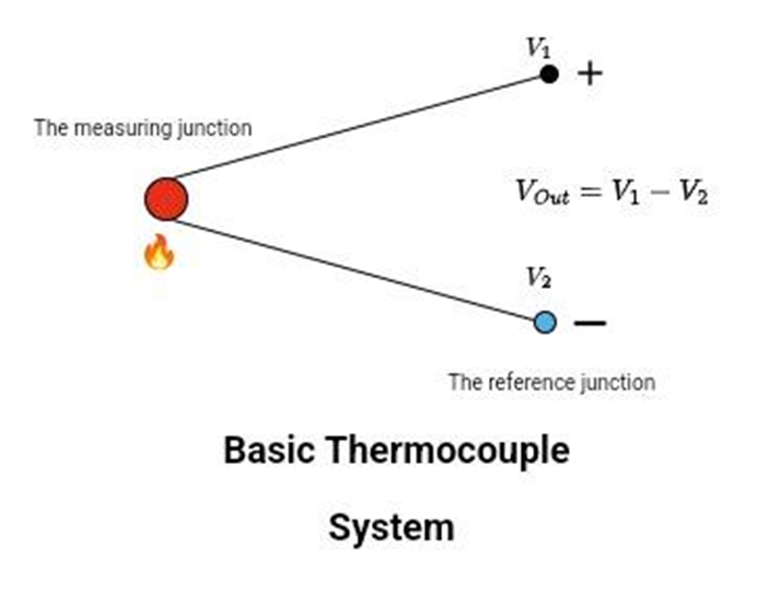
In thermocouples, two dissimilar metal wires are joined together, forming two junctions. The two metals have different conductivities at a given temperature. As the temperature rises, the conductivity difference also increases. Therefore, thermocouples are more reliable and efficient at higher temperatures. One of the junctions is known as the hot junction, while the other is known as the cold junction. The hot junction is also referred to as the measuring junction, while the other junction serves as the reference terminal. An electromotive force (EMF) is generated when there is a temperature change. The voltmeter will detect a voltage difference, measured in volts, that is directly proportional to the temperature difference between the hot and cold junctions.
Applications
- Temperature sensors are incorporated into industrial equipment to ensure safety and protection. These sensors are utilized for monitoring and controlling temperature. Hence, they are extensively utilized in applications such as heating, cooling, manufacturing, and storage processes.
- Temperature sensors are used in medical applications to accurately measure body temperature. They play a crucial role in temperature control for various medical devices and equipment.
- Temperature sensors play a vital role in the food and beverage industry. They are used for temperature monitoring and control in various processes such as food processing, storage, and transportation. Maintaining an optimal temperature is necessary to prevent potential food spoilage and ensure product quality.
Conclusion
The effectiveness of sensor types varies depending on the application they are used for, making it challenging to determine the definitive best choice. Multiple sensor types can adequately fulfill the requirements of many applications.
Analog sensors play a critical role in risk identification by alerting maintenance teams of any deviations from optimal operating conditions. Combined with a predictive maintenance strategy, sensors allow maintenance teams to perform corrective action, avoiding any potential failures.


